Ethernet Communication Module DVPEN01-SL
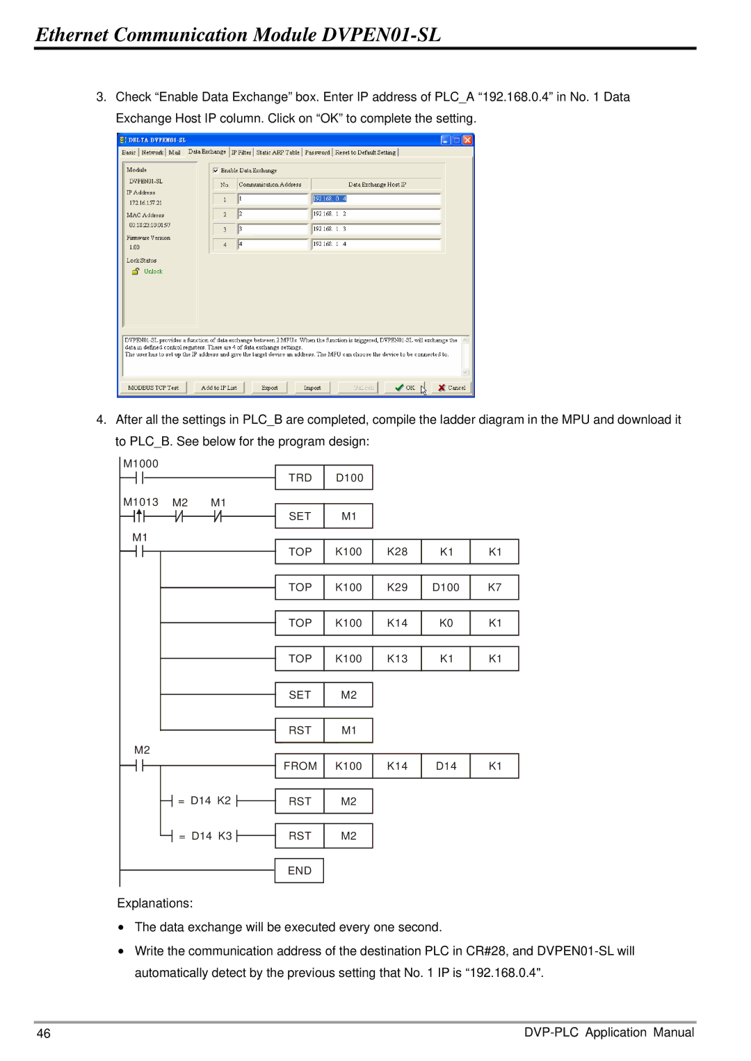
3.Check “Enable Data Exchange” box. Enter IP address of PLC_A “192.168.0.4” in No. 1 Data Exchange Host IP column. Click on “OK” to complete the setting.
4.After all the settings in PLC_B are completed, compile the ladder diagram in the MPU and download it to PLC_B. See below for the program design:
M1000 |
|
|
|
|
|
|
|
|
|
| TRD | D100 |
|
|
|
M1013 | M2 | M1 | SET | M1 |
|
|
|
|
|
|
|
|
| ||
M1 |
|
|
| K100 | K28 |
|
|
|
|
| TOP | K1 | K1 | ||
|
|
| TOP | K100 | K29 | D100 | K7 |
|
|
| TOP | K100 | K14 | K0 | K1 |
|
|
| TOP | K100 | K13 | K1 | K1 |
|
|
| SET | M2 |
|
|
|
|
|
| RST | M1 |
|
|
|
M2 |
|
|
|
|
|
|
|
|
|
| FROM | K100 | K14 | D14 | K1 |
| = D14 K2 | RST | M2 |
|
|
| |
| = D14 K3 | RST | M2 |
|
|
| |
|
|
| END |
|
|
|
|
Explanations: |
|
|
|
|
|
| |
•The data exchange will be executed every one second.
•Write the communication address of the destination PLC in CR#28, and
46 |