Ethernet Communication Module DVPEN01-SL
M1013 | M2 | M1 | SET | M1 |
|
|
|
|
|
|
|
|
| ||
M1 |
|
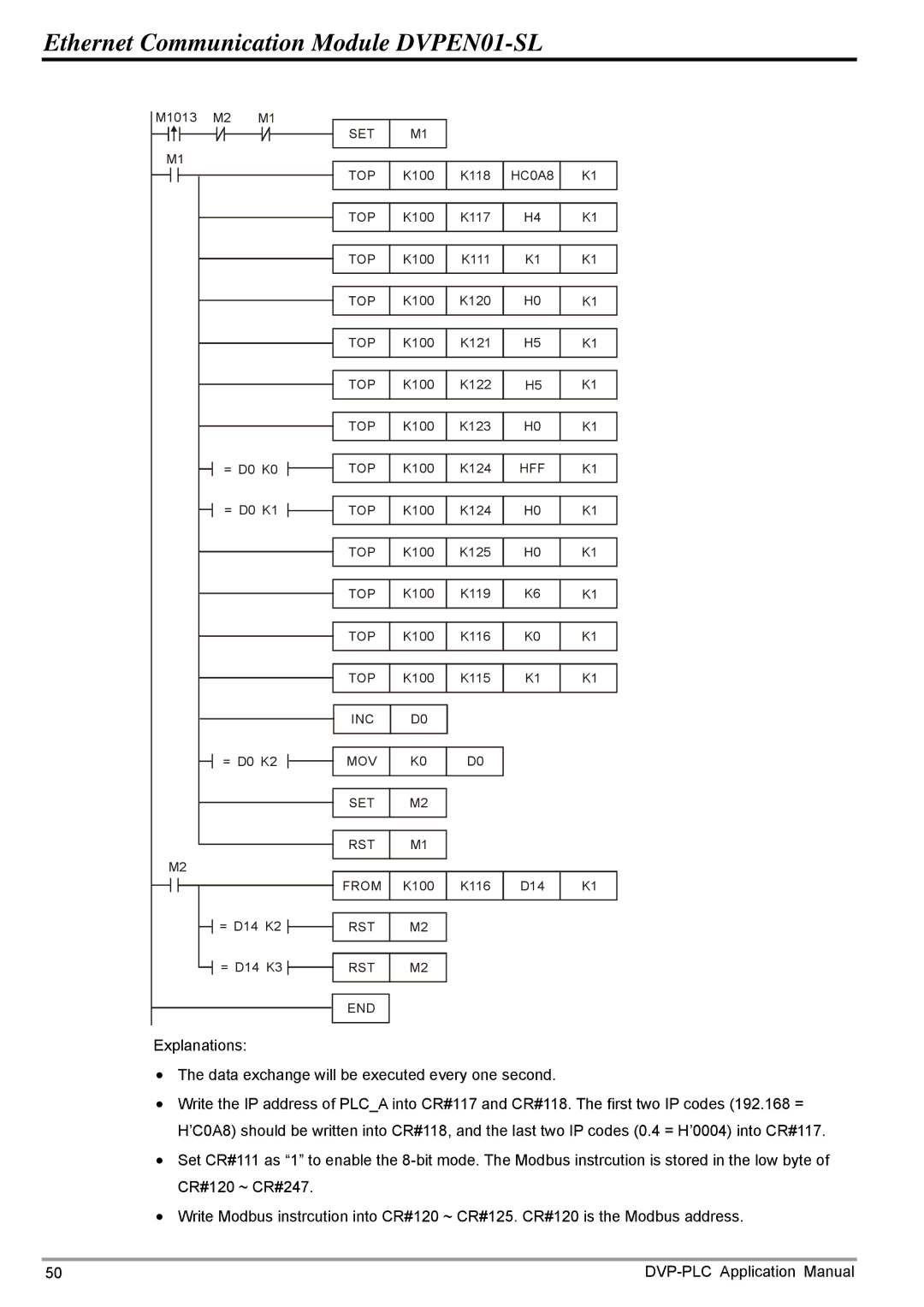
| TOP | K100 | K118 | HC0A8 | K1 |
|
|
| |||||
|
|
| TOP | K100 | K117 | H4 | K1 |
|
|
| TOP | K100 | K111 | K1 | K1 |
|
|
| TOP | K100 | K120 | H0 | K1 |
|
|
| TOP | K100 | K121 | H5 | K1 |
|
|
| TOP | K100 | K122 | H5 | K1 |
|
|
| TOP | K100 | K123 | H0 | K1 |
| = D0 K0 | TOP | K100 | K124 | HFF | K1 | |
| = D0 K1 | TOP | K100 | K124 | H0 | K1 | |
|
|
| TOP | K100 | K125 | H0 | K1 |
|
|
| TOP | K100 | K119 | K6 | K1 |
|
|
| TOP | K100 | K116 | K0 | K1 |
|
|
| TOP | K100 | K115 | K1 | K1 |
|
|
| INC | D0 |
|
|
|
| = D0 K2 | MOV | K0 | D0 |
|
| |
|
|
| SET | M2 |
|
|
|
|
|
| RST | M1 |
|
|
|
M2 |
|
|
|
|
|
|
|
|
|
| FROM | K100 | K116 | D14 | K1 |
| = D14 K2 | RST | M2 |
|
|
| |
| = D14 K3 | RST | M2 |
|
|
| |
|
|
| END |
|
|
|
|
Explanations: |
|
|
|
|
|
| |
•The data exchange will be executed every one second.
•Write the IP address of PLC_A into CR#117 and CR#118. The first two IP codes (192.168 = H’C0A8) should be written into CR#118, and the last two IP codes (0.4 = H’0004) into CR#117.
•Set CR#111 as “1” to enable the
•Write Modbus instrcution into CR#120 ~ CR#125. CR#120 is the Modbus address.
50 |