Ethernet Communication Module DVPEN01-SL
•Write the data in RTC into CR#29 ~ CR#35.
•Write “1” into CR#13 to start the data exchange.
•CR#14 = 2 refers to successful exchange. CR#14 = 3 refers to failed exchange.
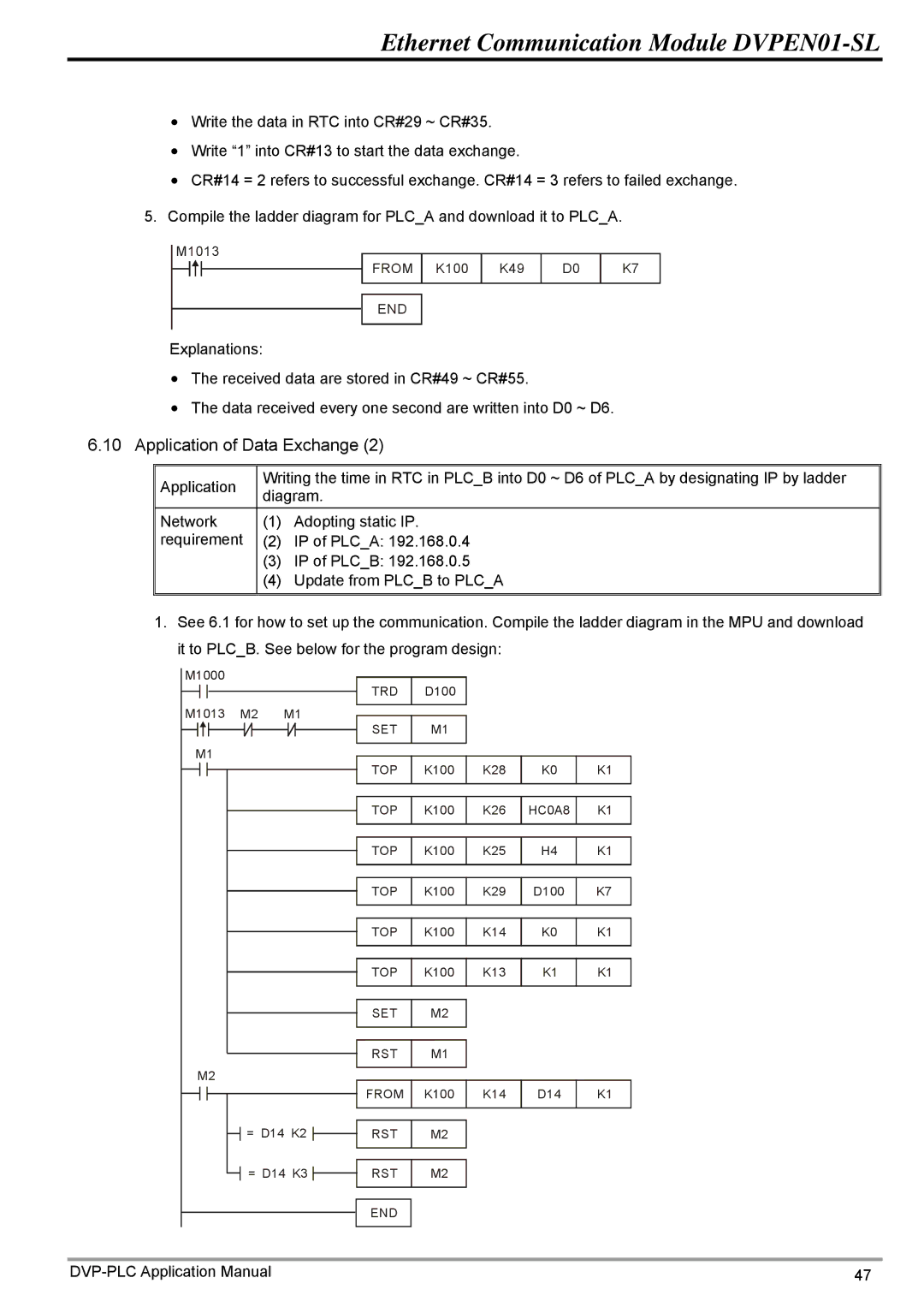
5.Compile the ladder diagram for PLC_A and download it to PLC_A.
M1013 |
|
|
|
|
FROM | K100 | K49 | D0 | K7 |
END |
|
|
|
|
Explanations: |
|
|
|
|
•The received data are stored in CR#49 ~ CR#55.
•The data received every one second are written into D0 ~ D6.
6.10Application of Data Exchange (2)
Application
Network requirement
Writing the time in RTC in PLC_B into D0 ~ D6 of PLC_A by designating IP by ladder diagram.
(1)Adopting static IP.
(2)IP of PLC_A: 192.168.0.4
(3)IP of PLC_B: 192.168.0.5
(4)Update from PLC_B to PLC_A
1.See 6.1 for how to set up the communication. Compile the ladder diagram in the MPU and download it to PLC_B. See below for the program design:
M1000 |
|
| TRD | D100 |
|
|
|
|
|
|
|
|
| ||
M1013 | M2 | M1 | SET | M1 |
|
|
|
|
|
|
|
|
| ||
M1 |
|
| TOP | K100 | K28 | K0 | K1 |
|
|
| |||||
|
|
| TOP | K100 | K26 | HC0A8 | K1 |
|
|
| TOP | K100 | K25 | H4 | K1 |
|
|
| TOP | K100 | K29 | D100 | K7 |
|
|
| TOP | K100 | K14 | K0 | K1 |
|
|
| TOP | K100 | K13 | K1 | K1 |
|
|
| SET | M2 |
|
|
|
|
|
| RST | M1 |
|
|
|
M2 |
|
|
|
|
|
|
|
|
|
| FROM | K100 | K14 | D14 | K1 |
| = D14 K2 | RST | M2 |
|
|
| |
| = D14 K3 | RST | M2 |
|
|
| |
|
|
| END |
|
|
|
|
47 |