Protection Functions

Display Keypads

Built-in Brake Chopper

Conditions

Protection Level

Pollution Degree


Installation Location

Enviromental

Ambient Temperature


Storage/Transportation


Temperature


Ambient Humidity


Vibration

Approvals

General Specifications

Self-testing, over voltage, over current, under voltage, overload, overheating, external fault, electronic thermal, ground fault.

6-key, 4-digit, 7-segment LED, 4 status LEDs, master frequency, output frequency, output current, custom units, parameter values for setup, review and faults, RUN,

STOP, RESET, FWD/REV Built-in for all models IP20

2

Altitude 1,000 m or lower, keep from corrosive gasses, liquid and dust

-10oC to 40oC (-10oC to 50oC without blind plate) Non-Condensing and not frozen

-20oC to 60oC

Below 90% RH (non-condensing)

9.80665m/s2 (1G) less than 20Hz, 5.88m/s2 (0.6G) at 20 to 50Hz

Note: Do not attempt to connect a single-phase power source to a three-phase models drive. However it is acceptable to connect two wires of a three-phase power source to a single-phase drive.

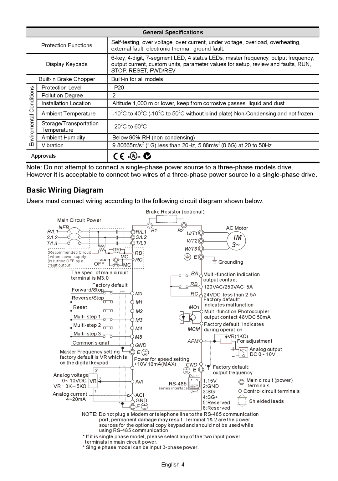
Basic Wiring Diagram

Users must connect wiring according to the following circuit diagram shown below.


Brake Resistor (optional)


Main Circuit Power


R/L1NFB


R/L1 B1

B2

U/T1

AC Motor

S/L2


S/L2


IM


V/T2


T/L3


T/L3


3~


SA


W/T3


Recommended Circuit


RB


MC


E


when power supply


RC


is turned OFF by a

OFF ON

MC


Grounding


fault output


The spec. of main circuit


RA

Multi-function indication

terminal is M3.0


output contact


Factory default


RB


120VAC/250VAC 5A

Forward/Stop


M0


RC

24VDC less than 2.5A

Reverse/Stop


M1


Factory default:


Reset


MO1

indicates malfunction


M2


Multi-step 1


Multi-function Photocoupler


M3


output contact 48VDC 50mA

Multi-step 2


Factory default: Indicates


M4


Multi-step 3


MCM during operation


M5


VR(1KΩ)


Common signal


GND


AFM

For adjustment


+

Analog output

Master Frequency setting


E


factory default is VR which is Power for speed setting

-

DC 010V


on the digital keypad


+10V 10mA(MAX) GND

Factory default:


3


E

Analog voltage


output frequency


RJ-11

VR 2


Main circuit (power)

010VDC


AVI

RS-485

1:15V

VR3K5KΩ


2:GND

terminals


series interface 6←1

Analog current

1


ACI

3:SG-

Control circuit terminals


4:SG+


GND


Shielded leads


5:Reserved


E


6:Reserved


NOTE: Do not plug a Modem or telephone line to the RS-485 communication port, permanent damage may result. Terminal 1& 2 are the power sources for the optional copy keypad and should not be used while using RS-485 communication.

*If it is single phase model, please select any of the two input power terminals in main circuit power.

*Single phase model can be input 3-phase power.

English-4

Page 4
Image 4
Delta Electronics VFD-XXXM quick start Basic Wiring Diagram, L1 NFB

VFD-XXXM specifications

Delta Electronics VFD-XXXM series represents a cutting-edge advancement in variable frequency drive (VFD) technology, catering to a diverse range of industrial applications. Designed for efficiency, reliability, and ease of integration, the VFD-XXXM series is an ideal choice for motor control systems in various sectors, including manufacturing, HVAC, and water treatment.

One of the standout features of the VFD-XXXM is its precise motor control capability. The drive supports multiple control modes, including V/f control, Vector Control, and Sensorless Vector Control, allowing users to optimize performance based on application needs. This flexibility ensures smooth operation and improved energy efficiency, making it suitable for both simple and complex motor tasks.

In terms of design, the VFD-XXXM series is compact and user-friendly. With an intuitive keypad and clear display, operators can easily navigate and configure the settings. This ease of use significantly reduces setup time and enhances operational efficiency. Additionally, the unit’s robust construction allows it to perform reliably in harsh industrial environments, with features such as IP20/IP55 protection ratings, making it resistant to dust and moisture.

One of the key technologies embedded in the VFD-XXXM is the Advanced Energy Saving Algorithm, which continuously optimizes the energy consumption of the connected motor. This feature not only reduces operational costs but also contributes to environmental sustainability initiatives by minimizing power waste.

The series boasts an extensive array of communication options, including Modbus, CANopen, and Ethernet interfaces, enabling seamless integration with existing automation systems. This connectivity enhances flexibility and allows for real-time monitoring and control, improving overall system performance.

Moreover, the VFD-XXXM includes comprehensive built-in safety features, such as overload protection, short circuit protection, and a safe torque off function. These safety characteristics ensure the protection of both the drive and the motor, promoting a secure operational environment.

In conclusion, Delta Electronics VFD-XXXM series stands out due to its advanced features, robust design, and energy-efficient technologies. Its versatility makes it an exceptional choice for varied industrial applications, providing businesses with reliable and sustainable motor control solutions that enhance both performance and efficiency.