®

MDVFST DIRECT-VENT GAS FIREPLACE

VENTING INSTALLATION

Continued

INSTALLATION FOR VERTICAL TERMINATION

NOTICE: Use rigid pipe only. Flex venting is NOT to be used with a vertical termination.

1.Determine the route your vertical vent- ing will take. If ceiling joists, roof rafters, or other framing will obstruct the vent- ing system, consider an offset (see Fig- ure 21) to avoid cutting loadbearing members. Note: Pay special attention to these installation instructions for re- quired clearances (air space) to combus- tibles when passing through ceilings, walls, roofs, enclosures, attic rafters, etc. Do not pack air spaces with insulation. Also note maximum vertical rise of the venting system and any maximum hori- zontal offset limitations. Offsets must fall within the parameters shown in Fig- ure 10 on page 5.

2.Set the fireplace in desired location. Drop a plumb line down from the ceil- ing to the position of the fireplace exit flue. Mark the center point where the vent will penetrate the ceiling. Drill a small locating hole at this point.

Drop a plumb line from the inside of the roof to the locating hole in the ceil- ing. Mark the center point where the vent will penetrate the roof. Drill a small locating hole at this point.

Roof

Flashing

Wall Strap

45° Elbow

Ceiling Firestop

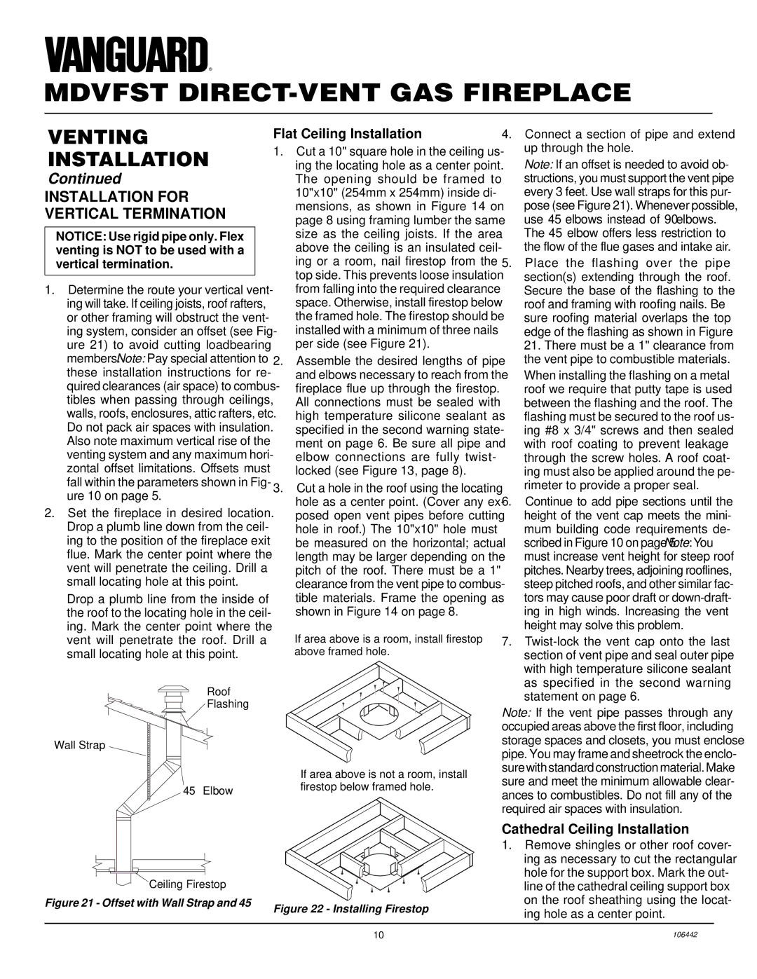
Figure 21 - Offset with Wall Strap and 45°

Flat Ceiling Installation

1.Cut a 10" square hole in the ceiling us- ing the locating hole as a center point. The opening should be framed to 10"x10" (254mm x 254mm) inside di- mensions, as shown in Figure 14 on page 8 using framing lumber the same size as the ceiling joists. If the area above the ceiling is an insulated ceil- ing or a room, nail firestop from the top side. This prevents loose insulation from falling into the required clearance space. Otherwise, install firestop below the framed hole. The firestop should be installed with a minimum of three nails per side (see Figure 21).

2.Assemble the desired lengths of pipe and elbows necessary to reach from the fireplace flue up through the firestop. All connections must be sealed with high temperature silicone sealant as specified in the second warning state- ment on page 6. Be sure all pipe and elbow connections are fully twist- locked (see Figure 13, page 8).

3.Cut a hole in the roof using the locating hole as a center point. (Cover any ex- posed open vent pipes before cutting hole in roof.) The 10"x10" hole must be measured on the horizontal; actual length may be larger depending on the pitch of the roof. There must be a 1" clearance from the vent pipe to combus- tible materials. Frame the opening as shown in Figure 14 on page 8.

If area above is a room, install firestop above framed hole.

If area above is not a room, install firestop below framed hole.

Figure 22 - Installing Firestop

4.Connect a section of pipe and extend up through the hole.

Note: If an offset is needed to avoid ob- structions, you must support the vent pipe every 3 feet. Use wall straps for this pur-

pose (see Figure 21). Whenever possible, use 45° elbows instead of 90° elbows. The 45° elbow offers less restriction to the flow of the flue gases and intake air.

5.Place the flashing over the pipe section(s) extending through the roof. Secure the base of the flashing to the roof and framing with roofing nails. Be sure roofing material overlaps the top edge of the flashing as shown in Figure 21. There must be a 1" clearance from the vent pipe to combustible materials.

When installing the flashing on a metal roof we require that putty tape is used between the flashing and the roof. The flashing must be secured to the roof us- ing #8 x 3/4" screws and then sealed with roof coating to prevent leakage through the screw holes. A roof coat- ing must also be applied around the pe- rimeter to provide a proper seal.

6.Continue to add pipe sections until the height of the vent cap meets the mini- mum building code requirements de- scribed in Figure 10 on page 5. Note: You must increase vent height for steep roof pitches. Nearby trees, adjoining rooflines, steep pitched roofs, and other similar fac- tors may cause poor draft or down-draft- ing in high winds. Increasing the vent height may solve this problem.

7.Twist-lock the vent cap onto the last section of vent pipe and seal outer pipe with high temperature silicone sealant as specified in the second warning statement on page 6.

Note: If the vent pipe passes through any occupied areas above the first floor, including storage spaces and closets, you must enclose pipe. You may frame and sheetrock the enclo- surewithstandardconstructionmaterial.Make sure and meet the minimum allowable clear- ances to combustibles. Do not fill any of the required air spaces with insulation.

Cathedral Ceiling Installation

1.Remove shingles or other roof cover- ing as necessary to cut the rectangular hole for the support box. Mark the out- line of the cathedral ceiling support box on the roof sheathing using the locat- ing hole as a center point.

10

106442

Page 10
Image 10
Desa MDVFST Installation for Vertical Termination, Flat Ceiling Installation, Cathedral Ceiling Installation

MDVFST specifications

Desa MDVFST, an innovative platform designed for multi-dimensional visualization and feature selection, is revolutionizing data analytics in various industries. The core objective of Desa MDVFST is to simplify the process of extracting meaningful insights from complex datasets, enabling analysts and decision-makers to make informed choices swiftly and effectively.

One of the standout features of Desa MDVFST is its ability to handle multi-dimensional data with ease. It employs advanced algorithms to visualize relationships between various data points, allowing users to discern patterns that might be obscured in traditional data analysis methods. This multi-dimensional approach contributes significantly to enhanced data comprehension, leading to more accurate predictions and strategic decisions.

Desa MDVFST is built on a robust technology stack that includes machine learning and artificial intelligence. These technologies are integrated into the platform to automate feature selection, a process critical in identifying the most relevant variables that impact performance. By leveraging machine learning algorithms, Desa MDVFST minimizes human error and enhances efficiency, leading to faster project completion times without sacrificing quality.

Another remarkable characteristic of Desa MDVFST is its user-friendly interface, designed for professionals across various technical backgrounds. This democratization of data analysis ensures that stakeholders from different sectors can utilize the platform without extensive training. The interface allows users to manipulate datasets interactively, providing real-time insights and visualizations that facilitate better decision-making.

Moreover, Desa MDVFST emphasizes scalability, ensuring that businesses can adapt the platform to varying data sizes and complexities. Whether a small enterprise or a large corporation, users can tailor the platform to meet their specific needs, making it a versatile solution for a wide range of applications, from marketing analytics to financial forecasting.

In addition, Desa MDVFST incorporates cloud technology, enhancing accessibility and collaboration among team members. Users can access the platform from any location, ensuring that teams can work together seamlessly, regardless of geographical boundaries.

In conclusion, Desa MDVFST is an advanced tool set to transform the landscape of data analytics with its multi-dimensional visualization capabilities, machine learning-driven feature selection, user-friendly interface, scalability, and cloud accessibility. As businesses increasingly rely on data-driven strategies, Desa MDVFST emerges as a vital resource in achieving actionable insights and a competitive edge in the marketplace.