Fireplace
Installation
Continued
Test Pressures Equal To or Less Than
1/2 PSIG (3.5 kPa)
1. Close equipment shutoff valve (see Figure 33).
2. Pressurize supply piping system by either opening propane/LP supply tank valve for propane/LP gas fireplace or opening main gas valve located on or near gas meter for natural gas fireplace or using compressed air.
3. Check all joints from propane/LP supply tank for propane/LP or gas meter for natural gas to equipment shutoff valve (see Figure 34 or Figure 35). Apply noncorrosive leak detection fluid to all joints. Bubbles forming show a leak. Correct all leaks at once.
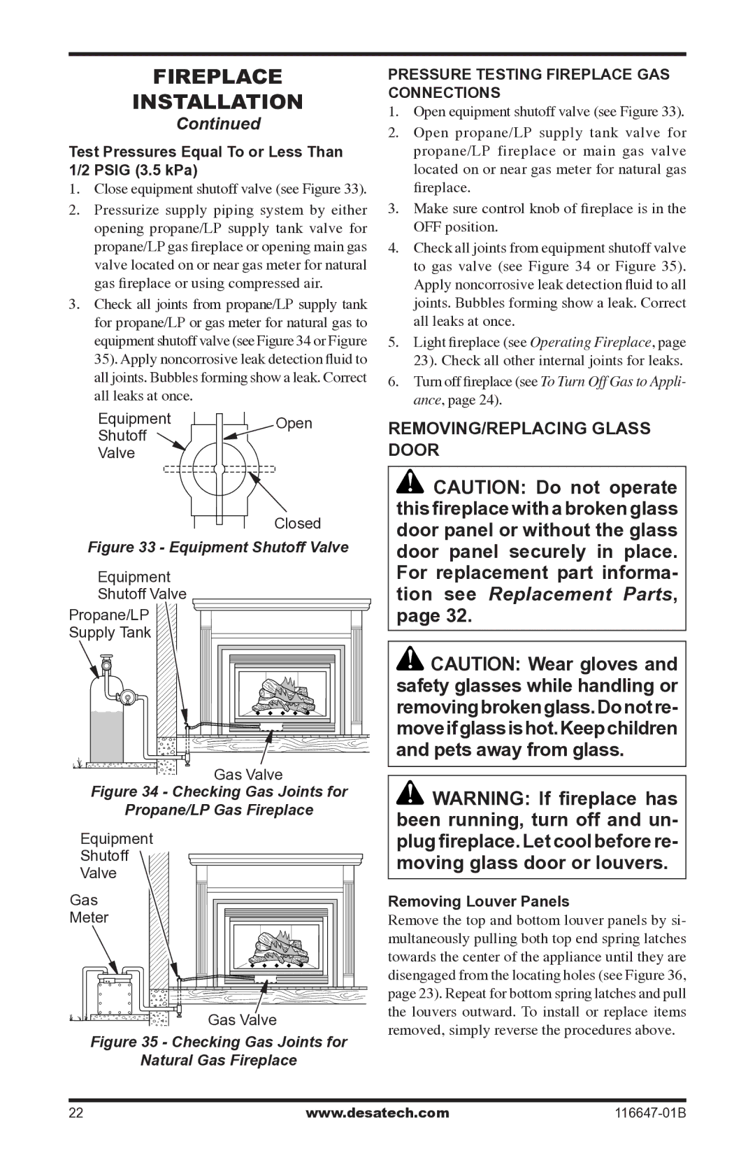
EquipmentOpen
Shutoff
Valve
Closed
Figure 33 - Equipment Shutoff Valve
Equipment |
Shutoff Valve |
Propane/LP |
Supply Tank |
Gas Valve |
Figure 34 - Checking Gas Joints for |
Propane/LP Gas Fireplace |
Equipment |
Shutoff |
Valve |
Gas |
Meter |
Gas Valve |
Figure 35 - Checking Gas Joints for
Natural Gas Fireplace
Pressure Testing Fireplace Gas
Connections
1. Open equipment shutoff valve (see Figure 33).
2. Open propane/LP supply tank valve for propane/LP fireplace or main gas valve located on or near gas meter for natural gas fireplace.
3. Make sure control knob of fireplace is in the OFF position.
4. Check all joints from equipment shutoff valve to gas valve (see Figure 34 or Figure 35). Apply noncorrosive leak detection fluid to all joints. Bubbles forming show a leak. Correct all leaks at once.
5. Light fireplace (see Operating Fireplace, page
23). Check all other internal joints for leaks.
6. Turn off fireplace (see To Turn Off Gas to Appli- ance, page 24).
Removing/Replacing Glass
Door
![]() CAUTION: Do not operate this fireplace with a broken glass door panel or without the glass door panel securely in place. For replacement part informa- tion see Replacement Parts, page 32.
CAUTION: Do not operate this fireplace with a broken glass door panel or without the glass door panel securely in place. For replacement part informa- tion see Replacement Parts, page 32.
![]() CAUTION: Wear gloves and safety glasses while handling or removingbrokenglass.Donotre- moveifglassishot.Keepchildren and pets away from glass.
CAUTION: Wear gloves and safety glasses while handling or removingbrokenglass.Donotre- moveifglassishot.Keepchildren and pets away from glass.
![]() WARNING: If fireplace has been running, turn off and un- plug fireplace. Let cool before re- moving glass door or louvers.
WARNING: If fireplace has been running, turn off and un- plug fireplace. Let cool before re- moving glass door or louvers.
Removing Louver Panels
Remove the top and bottom louver panels by si- multaneously pulling both top end spring latches towards the center of the appliance until they are disengaged from the locating holes (see Figure 36, page 23). Repeat for bottom spring latches and pull the louvers outward. To install or replace items removed, simply reverse the procedures above.
22 | www.desatech.com |