INTERNAL SETTINGS
9.1.1 Low Cut Filter
The four MIC/LINE-inputs provide switch-able Low Cut filter (85 Hz / 12 dB per octave), which cut-off frequencies below 85 Hz. The use of the Low Cut filters is especially recommendable for microphone applications, effectively eliminating low-frequency feedback and ambient sound as well as popping sounds, which results in increased vocal intelligibility. An additional side-effect is that your power amplifier and loudspeaker systems do not have to handle unwanted low-frequency signals cluttering your entire sound system.
The Low Cut filters in the MIC/LINE-input channels are enabled in the factory pre-set state. They can be disabled via internal jumpers when, for instance, connecting LINE-level signal source.
MIC/LINEChannel | Jumpers |
1 | S1A |
2 | S1B |
3 | S1C |
4 | S1D |
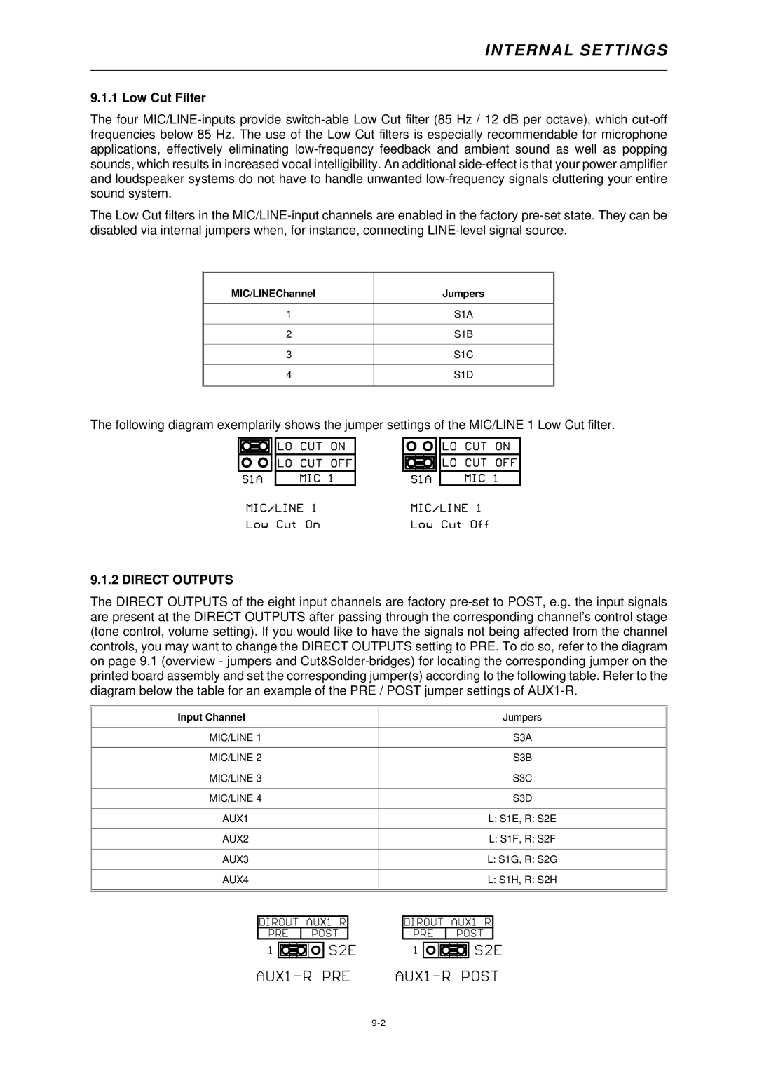
The following diagram exemplarily shows the jumper settings of the MIC/LINE 1 Low Cut filter.
9.1.2 DIRECT OUTPUTS
The DIRECT OUTPUTS of the eight input channels are factory pre-set to POST, e.g. the input signals are present at the DIRECT OUTPUTS after passing through the corresponding channel’s control stage (tone control, volume setting). If you would like to have the signals not being affected from the channel controls, you may want to change the DIRECT OUTPUTS setting to PRE. To do so, refer to the diagram on page 9.1 (overview - jumpers and Cut&Solder-bridges) for locating the corresponding jumper on the printed board assembly and set the corresponding jumper(s) according to the following table. Refer to the diagram below the table for an example of the PRE / POST jumper settings of AUX1-R.
Input Channel | Jumpers |
MIC/LINE 1 | S3A |
MIC/LINE 2 | S3B |
MIC/LINE 3 | S3C |
MIC/LINE 4 | S3D |
AUX1 | L: S1E, R: S2E |
AUX2 | L: S1F, R: S2F |
AUX3 | L: S1G, R: S2G |
AUX4 | L: S1H, R: S2H |