Contents
DRM
Safety Component has to be Replaced with Original Part only
For US, Canada and Japan only
Contents
Introduction
Introduction DRM 4000 Characteristics
Characteristics
Field of Application
Unpacking and Warranty
Controls and Connections
Controls and Connections
Tone Control LO / HI
Ducking indicators a / B
12, POWER-switch
Control AUX
16, Control
18, Direct OUT
20, Send output
26, PAD-switch
27, +24V-switch
21, MIX in input
Uick Start
Quick Start
General Notes
Installation and Connections
Installation and Connections
Input Assignment 1 MIC/LINE inputs
Send outputs
AUX and MIX in inputs
Output Assignment 4.3.1 Master outputs
Direct Outputs
External VCA-Control
Control Inputs
Control Inputs
Level Adjustment for MIC/LINE-inputs
Power-On Operation
Level Settings
Initial Operation
Level Adjustment for AUX-inputs
Using Ducking Control
Special Features of the DRM
Special Features of the DRM
Limiter Operation
Using The Unit Together With The DPM
Software Editor DRM
Installation Notes
Software Editor DRM
System Requirements
Software Description 7.4.1 General
Menus And The Toolbar File Menu
Communication Menu
Basic Configuration
View Menu
About Menu
Aux-inputs
Name and Comment
MIC/LINE-inputs
Outputs
Priority
Test
Online Control / Status
Control Inputs View Status
Configuring the DRM
N Figuring the DRM
Basic Configuration
Internal Configuration Possibilities
Internal Settings
Internal Settings / Extensions
Low Cut Filter
Limiter Settings
AUX Sensitivity Selection
HOW to Install Extensions
How to install the Input Transformer NRS 90233, EDP-No
How to install the Output Transformer NRS 90227, EDP-No
How to install Interface-Boards
Peci F I C a T IO N S
Specifications
Specifications
User Configuration
Specific a Tions
Specifica Tions
Block diagram
Switching Contacts Via Software
10.4 RS-232 Interface Programmer’s Instructions
Online-Access to all Parameters
REMOTE/PRIO value
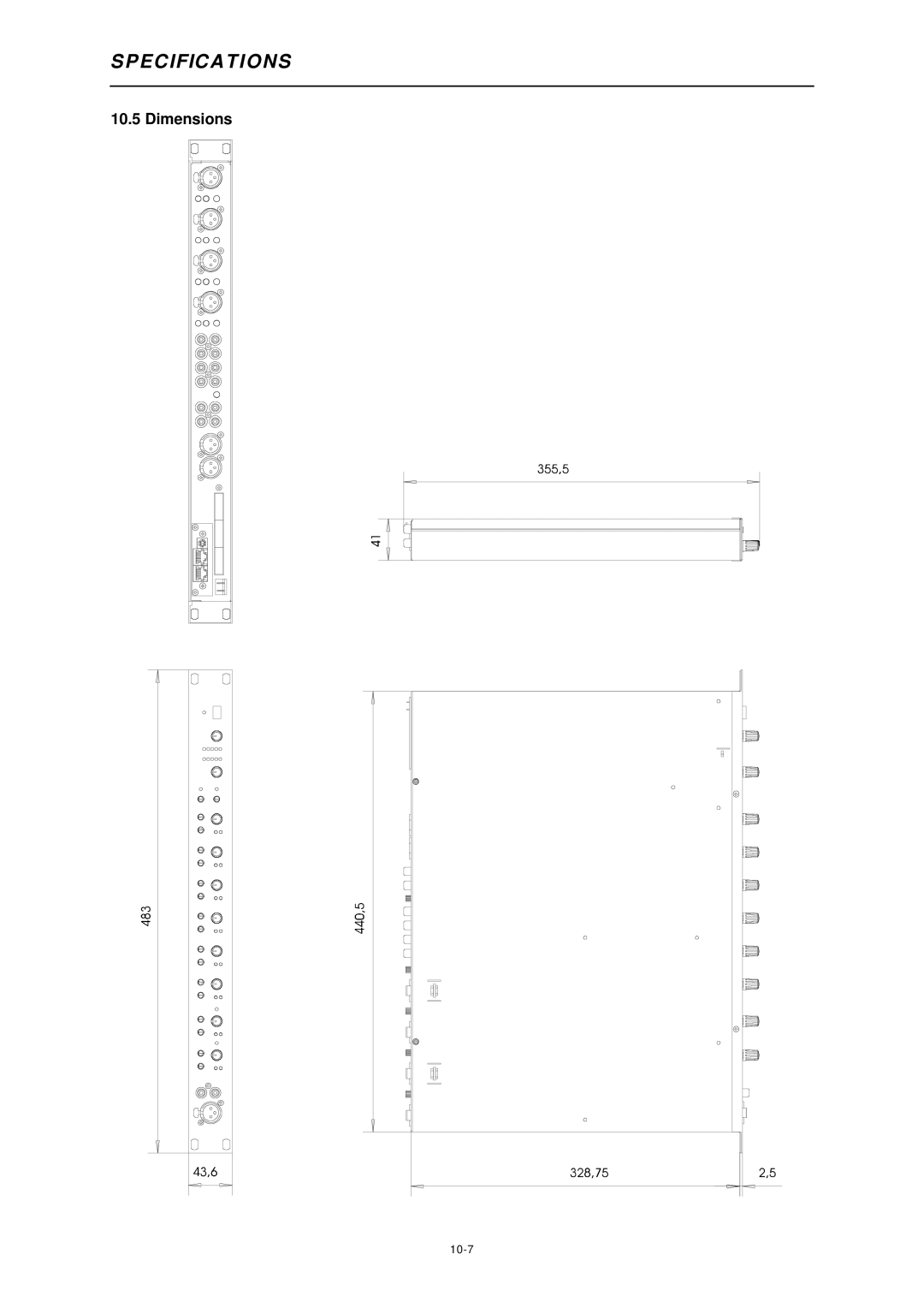
Dimensions
Warranty
Garantie