INTERNAL SETTINGS
9.1.3 AUX Sensitivity Selection
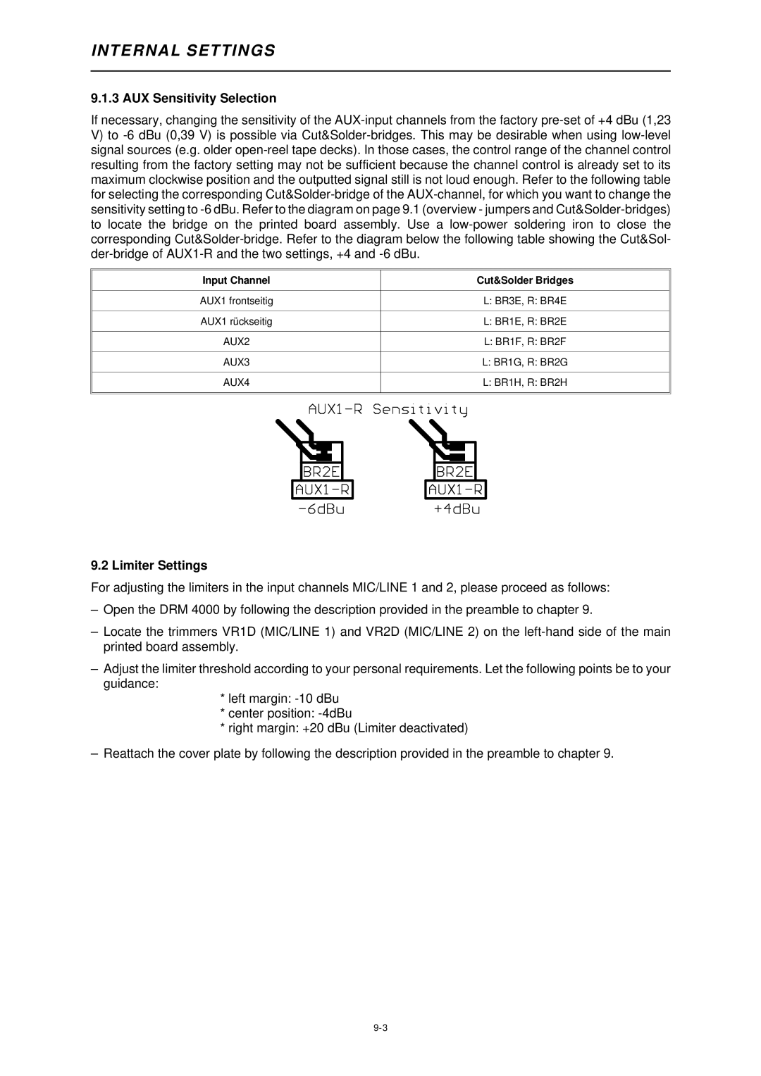
If necessary, changing the sensitivity of the AUX-input channels from the factory pre-set of +4 dBu (1,23
V)to -6 dBu (0,39 V) is possible via Cut&Solder-bridges. This may be desirable when using low-level signal sources (e.g. older open-reel tape decks). In those cases, the control range of the channel control resulting from the factory setting may not be sufficient because the channel control is already set to its maximum clockwise position and the outputted signal still is not loud enough. Refer to the following table for selecting the corresponding Cut&Solder-bridge of the AUX-channel, for which you want to change the sensitivity setting to -6 dBu. Refer to the diagram on page 9.1 (overview - jumpers and Cut&Solder-bridges) to locate the bridge on the printed board assembly. Use a low-power soldering iron to close the corresponding Cut&Solder-bridge. Refer to the diagram below the following table showing the Cut&Sol- der-bridge of AUX1-R and the two settings, +4 and -6 dBu.
Input Channel | | | | Cut&Solder Bridges |
AUX1 frontseitig | | | | L: BR3E, R: BR4E |
AUX1 rückseitig | | | | L: BR1E, R: BR2E |
AUX2 | | | | L: BR1F, R: BR2F |
AUX3 | | | | L: BR1G, R: BR2G |
AUX4 | | | | L: BR1H, R: BR2H |
| | | | |
| | | | |
| | | | |
| | | | |
9.2 Limiter Settings
For adjusting the limiters in the input channels MIC/LINE 1 and 2, please proceed as follows:
–Open the DRM 4000 by following the description provided in the preamble to chapter 9.
–Locate the trimmers VR1D (MIC/LINE 1) and VR2D (MIC/LINE 2) on the left-hand side of the main printed board assembly.
–Adjust the limiter threshold according to your personal requirements. Let the following points be to your guidance:
*left margin: -10 dBu
*center position: -4dBu
*right margin: +20 dBu (Limiter deactivated)
–Reattach the cover plate by following the description provided in the preamble to chapter 9.