CONTROLS AND CONNECTIONS
2. CONTROLS AND CONNECTIONS
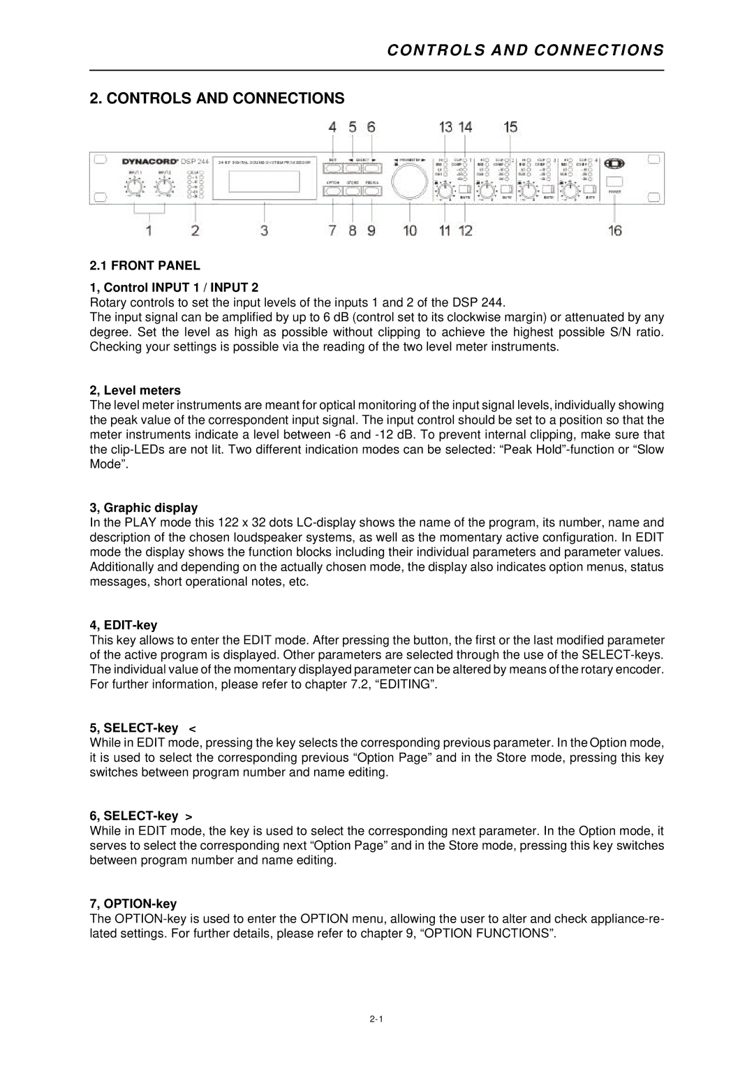
2.1 FRONT PANEL
1, Control INPUT 1 / INPUT 2
Rotary controls to set the input levels of the inputs 1 and 2 of the DSP 244.
The input signal can be amplified by up to 6 dB (control set to its clockwise margin) or attenuated by any degree. Set the level as high as possible without clipping to achieve the highest possible S/N ratio. Checking your settings is possible via the reading of the two level meter instruments.
2, Level meters
The level meter instruments are meant for optical monitoring of the input signal levels, individually showing the peak value of the correspondent input signal. The input control should be set to a position so that the meter instruments indicate a level between
3, Graphic display
In the PLAY mode this 122 x 32 dots
4, EDIT-key
This key allows to enter the EDIT mode. After pressing the button, the first or the last modified parameter of the active program is displayed. Other parameters are selected through the use of the
5, SELECT-key <
While in EDIT mode, pressing the key selects the corresponding previous parameter. In the Option mode, it is used to select the corresponding previous “Option Page” and in the Store mode, pressing this key switches between program number and name editing.
6,
While in EDIT mode, the key is used to select the corresponding next parameter. In the Option mode, it serves to select the corresponding next “Option Page” and in the Store mode, pressing this key switches between program number and name editing.
7, OPTION-key
The
