Important Note: If the UPS is used in Single Mode, JP1 and JP2 must be connected by 10AWG (6mm2). If the UPS is used in Parallel Mode, the Jumper between JP1 and JP2 must be removed.
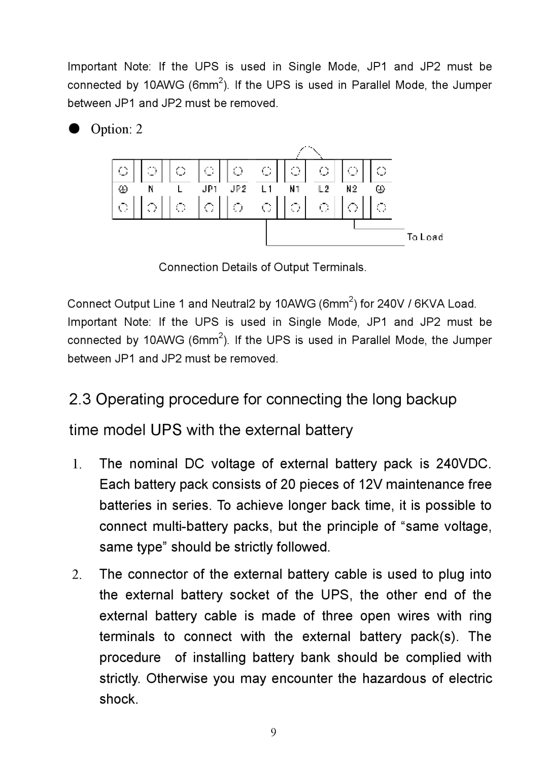
●Option: 2
Connection Details of Output Terminals.
Connect Output Line 1 and Neutral2 by 10AWG (6mm2) for 240V / 6KVA Load. Important Note: If the UPS is used in Single Mode, JP1 and JP2 must be connected by 10AWG (6mm2). If the UPS is used in Parallel Mode, the Jumper between JP1 and JP2 must be removed.
2.3Operating procedure for connecting the long backup time model UPS with the external battery
1.The nominal DC voltage of external battery pack is 240VDC. Each battery pack consists of 20 pieces of 12V maintenance free batteries in series. To achieve longer back time, it is possible to connect
2.The connector of the external battery cable is used to plug into the external battery socket of the UPS, the other end of the external battery cable is made of three open wires with ring terminals to connect with the external battery pack(s). The procedure of installing battery bank should be complied with strictly. Otherwise you may encounter the hazardous of electric shock.
9
