Installation Drawings
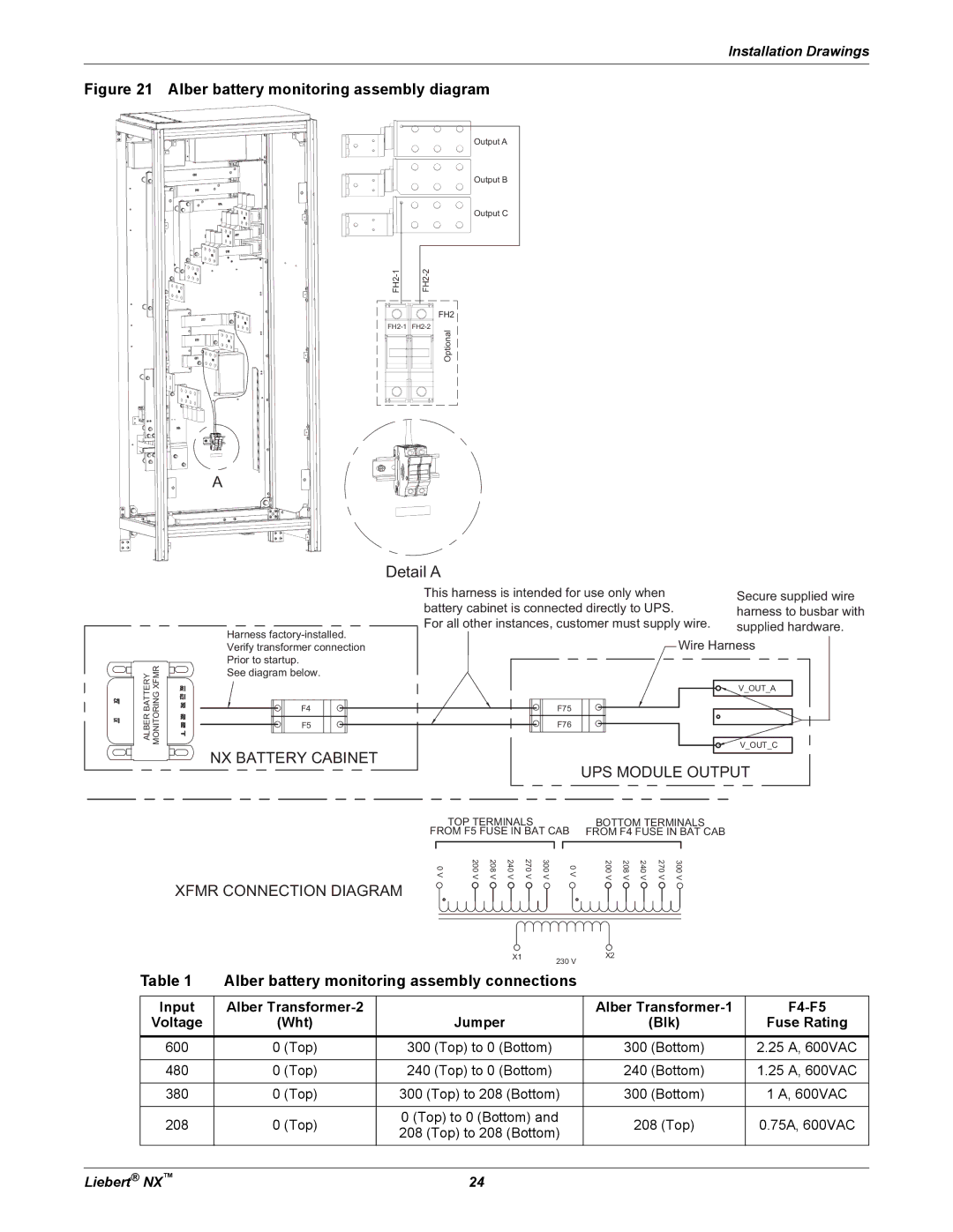
Figure 21 Alber battery monitoring assembly diagram
|
|
|
| ||
|
|
|
| ||
|
|
|
|
|
|
|
|
|
|
|
|
![]()
Output A
Output B
Output C
FH2
Optional
A
ALBER BATTERY MONITORING XFMR
Detail A
|
|
|
|
|
|
| This harness is intended for use only when |
|
|
| Secure supplied wire | ||||||||||||||||||||||
|
|
|
|
|
|
| battery cabinet is connected directly to UPS. |
|
|
| harness to busbar with | ||||||||||||||||||||||
|
|
|
|
|
|
| For all other instances, customer must supply wire. | supplied hardware. | |||||||||||||||||||||||||
Harness |
|
|
|
|
|
|
|
|
|
|
|
|
|
|
|
|
| Wire Harness |
|
| |||||||||||||
Verify transformer connection |
|
|
|
|
|
|
|
|
|
|
|
|
|
|
|
|
|
| |||||||||||||||
|
|
|
|
|
|
|
|
|
|
|
|
|
|
|
|
| |||||||||||||||||
Prior to startup. |
|
|
|
|
|
|
|
|
|
|
|
|
|
|
|
|
|
|
|
|
|
|
|
|
| ||||||||
See diagram below. |
|
|
|
|
|
|
|
|
|
|
|
|
|
|
|
|
|
|
|
|
|
|
|
|
| ||||||||
|
|
|
|
|
|
|
|
|
|
|
|
|
|
|
|
|
|
|
|
|
|
|
|
|
|
|
|
| V_OUT_A |
|
|
|
|
|
|
|
|
|
|
|
|
|
|
|
|
|
|
|
|
|
|
|
|
|
|
|
|
|
|
|
|
|
|
|
|
| |
|
|
|
|
|
|
|
|
|
|
|
|
|
|
|
|
|
|
|
|
|
|
|
|
|
|
|
|
|
|
|
|
|
|
|
|
| F4 |
|
|
|
|
|
|
|
|
|
|
|
| F75 |
|
|
|
|
|
|
|
|
|
|
|
|
|
|
|
| |
|
|
| F5 |
|
|
|
|
|
|
|
|
|
|
|
| F76 |
|
|
|
|
|
|
|
|
|
|
|
|
|
|
|
| |
|
|
|
|
|
|
|
|
|
|
|
|
|
|
|
|
|
|
|
|
|
|
|
|
|
|
|
|
|
|
| |||
|
|
|
|
|
|
|
|
|
|
|
|
|
|
|
|
|
|
|
|
|
|
|
|
|
|
|
| ||||||
|
|
|
|
|
|
|
|
|
|
|
|
|
|
|
|
|
|
|
|
|
|
|
|
|
|
|
|
|
|
|
|
|
|
NX BATTERY CABINET |
|
|
|
|
|
|
|
|
|
|
|
|
|
|
|
|
|
|
|
| V_OUT_C |
|
|
|
| ||||||||
|
|
|
|
|
|
|
|
|
|
|
|
|
|
|
|
|
|
|
|
|
|
|
| ||||||||||
|
|
|
|
|
|
|
|
|
|
|
|
|
|
|
|
|
|
|
|
|
|
|
|
| |||||||||
|
|
|
|
|
|
|
|
| UPS MODULE OUTPUT | ||||||||||||||||||||||||
|
|
|
|
|
|
|
|
|
|
|
|
|
|
|
|
|
| ||||||||||||||||
|
|
|
|
|
|
|
|
| TOP TERMINALS |
|
|
|
| BOTTOM TERMINALS |
|
|
|
|
| ||||||||||||||
|
|
|
|
|
|
| FROM F5 FUSE IN BAT CAB | FROM F4 FUSE IN BAT CAB |
|
|
|
|
| ||||||||||||||||||||
|
|
|
|
|
|
|
|
| 200 V | 208 V | 240 V | 270 V | 300 V |
|
|
|
|
|
|
|
| 270 V |
|
|
|
|
|
|
|
| |||
|
|
|
|
|
|
|
| 0 V |
| 0 V |
|
|
| 200 V | 208 V | 240 V | 300 V |
|
|
|
|
| |||||||||||
XFMR CONNECTION DIAGRAM
|
| X1 | 230 V | X2 |
| |
|
|
|
|
| ||
Table 1 | Alber battery monitoring assembly connections |
|
| |||
|
|
|
|
|
| |
Input | Alber |
|
| Alber | ||
Voltage | (Wht) | Jumper |
| (Blk) | Fuse Rating | |
600 | 0 (Top) | 300 (Top) to 0 (Bottom) |
| 300 (Bottom) | 2.25 A, 600VAC | |
|
|
|
|
|
| |
480 | 0 (Top) | 240 (Top) to 0 (Bottom) |
| 240 (Bottom) | 1.25 A, 600VAC | |
|
|
|
|
| ||
380 | 0 (Top) | 300 (Top) to 208 (Bottom) | 300 (Bottom) | 1 A, 600VAC | ||
|
|
|
|
| ||
208 | 0 (Top) | 0 (Top) to 0 (Bottom) and | 208 (Top) | 0.75A, 600VAC | ||
208 (Top) to 208 (Bottom) | ||||||
|
|
|
| |||
Liebert® NX™ | 24 |