Installation Drawings
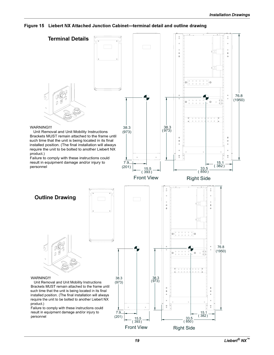
Figure 15 Liebert NX Attached Junction Cabinet—terminal detail and outline drawing
Terminal Details
WARNING!!!
Unit Removal and Unit Mobility Instructions Brackets MUST remain attached to the frame until such time that the unit is being located in its final installed position. (The final installation will always require the unit to be bolted to another Liebert NX
product.)
Failure to comply with these instructions could result in equipment damage and/or injury to personnel
38.3 |
|
(973) |
|
7.9 |
|
(201) | 15.5 |
| ( 393) |
Front View
38.3
(973)
76.8
(1950)
15.1 ( 382)
33.5 ( 850)
Right Side
Outline Drawing
WARNING!!!
Unit Removal and Unit Mobility Instructions Brackets MUST remain attached to the frame until such time that the unit is being located in its final installed position. (The final installation will always require the unit to be bolted to another Liebert NX
product.)
Failure to comply with these instructions could result in equipment damage and/or injury to personnel
38.3 |
|
(973) |
|
7.9 |
|
(201) | 15.5 |
| |
| ( 393 ) |
Front View
38.3 (973)
76.8
(1950)
15.1 ( 382 )
33.5 ( 850 )
Right Side
19 | Liebert® NX™ |