99
APPENDIX A - SITE PLANNING DATA, SERIES 610,
Site Planning
Notes for Tables 6 - 7
1.Nominal rectifier AC input current (considered continuous) is based on full rated output load. Maximum current includes nominal input current and maximum battery recharge current (considered noncontinuous). Continuous and noncontinuous current limits are defined in NEC 100. Maximum input current is controlled by current limit setting which is adjustable 100 to 125% of nominal input
2.Nominal AC output current (considered continuous) is based on full rated output load. Maximum current includes nominal output current and overload current for 10 minutes.
3.Bypass AC input current (considered continuous) is based on full rated output load.
4.Feeder protection (by others in external equipment) for rectifier AC input and bypass AC input is recommended to be provided by separate overcurrent protection devices.
5.UPS output load cables must be run in separate conduit from input cables.
6.Power cable from module DC bus to battery should be sized for a total maximum 2.0 volt line drop (power cable drop plus return cable drop as measured at the module) at maximum discharge current.
7.Grounding conductors to be sized per NEC
(7 continued)
NOTE: A neutral conductor is required from each
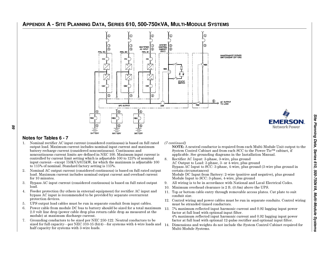
8.Rectifier AC Input:
AC Output to Load:
Bypass AC Input to SCC:
Module DC Input from Battery:
Module Input to SCC:
9.All wiring is to be in accordance with National and Local Electrical Codes.
10.Minimum overhead clearance is 2 ft. (0.6m) above the UPS.
11.Top or bottom cable entry through removable access plates. Cut plate to suit conduit size.
12.Control wiring and power cables must be run in separate conduits. Control wiring must be stranded tinned conductors.
13.7% maximum reflected input harmonic current and 0.92 lagging input power factor at full load with optional input filter.
4% maximum reflected input harmonic current and 0.92 lagging input power factor at full load with optional
14.Dimensions and weights do not include the System Control Cabinet required for