Configuring Your Neutral and Ground Connections
6.3Preferred Grounding Configuration With Isolated Bypass
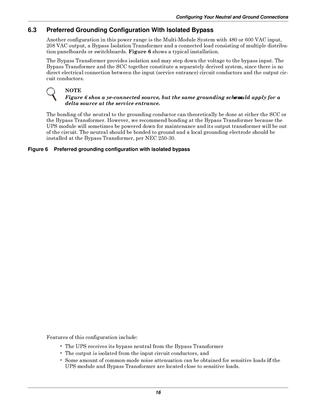
Another configuration in this power range is the
The Bypass Transformer provides isolation and may step down the voltage to the bypass input. The Bypass Transformer and the SCC together constitute a separately derived system, since there is no direct electrical connection between the input (service entrance) circuit conductors and the output cir- cuit conductors.
NOTE
Figure 6 shows a wye-connected source, but the same grounding scheme would apply for a delta source at the service entrance.
The bonding of the neutral to the grounding conductor can theoretically be done at either the SCC or the Bypass Transformer. However, we recommend bonding at the Bypass Transformer because the UPS module will sometimes be powered down for maintenance and its output transformer will be out of the circuit. The neutral should be bonded to ground and a local grounding electrode should be installed at the Bypass Transformer, per NEC
Figure 6 Preferred grounding configuration with isolated bypass
Features of this configuration include:
•The UPS receives its bypass neutral from the Bypass Transformer
•The output is isolated from the input circuit conductors, and
•Some amount of
16