SECTION B
Assembly Instructions for Installing the CF2600 and CF2650 Ceiling Fan Controlled by Emerson Fan/Light Controls (other than SR330 or SW350) or Standard Wall Switches
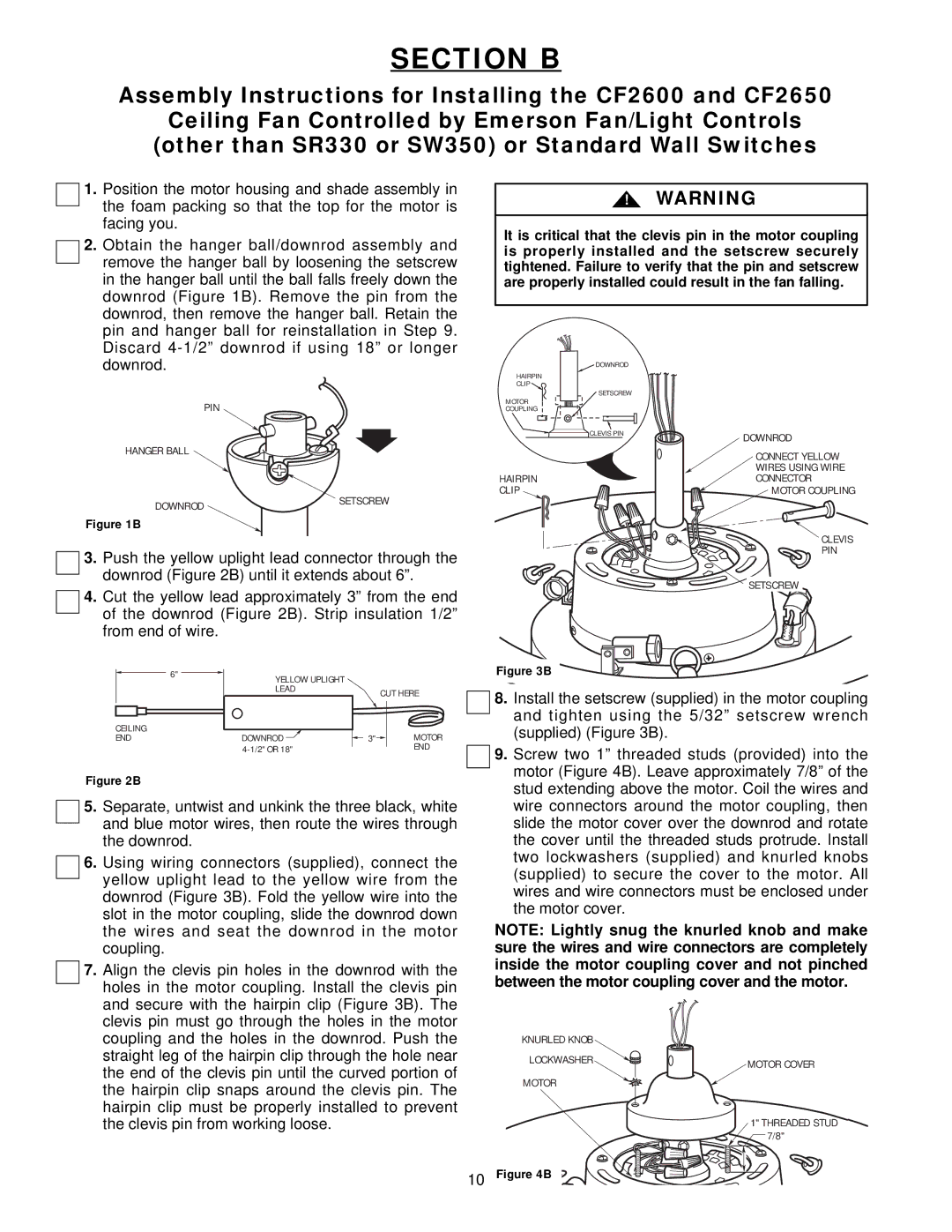
1.Position the motor housing and shade assembly in the foam packing so that the top for the motor is facing you.
2.Obtain the hanger ball/downrod assembly and remove the hanger ball by loosening the setscrew in the hanger ball until the ball falls freely down the downrod (Figure 1B). Remove the pin from the downrod, then remove the hanger ball. Retain the pin and hanger ball for reinstallation in Step 9. Discard
PIN
HANGER BALL
DOWNROD | SETSCREW |
|
Figure 1B
3.Push the yellow uplight lead connector through the downrod (Figure 2B) until it extends about 6”.
4.Cut the yellow lead approximately 3” from the end of the downrod (Figure 2B). Strip insulation 1/2” from end of wire.
| 6" | YELLOW UPLIGHT |
|
|
|
| LEAD |
| CUT HERE |
|
|
|
| |
CEILING |
|
|
| MOTOR |
END |
| DOWNROD | 3" | |
|
|
| END |
Figure 2B
5.Separate, untwist and unkink the three black, white and blue motor wires, then route the wires through the downrod.
6.Using wiring connectors (supplied), connect the yellow uplight lead to the yellow wire from the downrod (Figure 3B). Fold the yellow wire into the slot in the motor coupling, slide the downrod down the wires and seat the downrod in the motor coupling.
7.Align the clevis pin holes in the downrod with the holes in the motor coupling. Install the clevis pin and secure with the hairpin clip (Figure 3B). The clevis pin must go through the holes in the motor coupling and the holes in the downrod. Push the straight leg of the hairpin clip through the hole near the end of the clevis pin until the curved portion of the hairpin clip snaps around the clevis pin. The hairpin clip must be properly installed to prevent the clevis pin from working loose.
!WARNING
It is critical that the clevis pin in the motor coupling is properly installed and the setscrew securely tightened. Failure to verify that the pin and setscrew are properly installed could result in the fan falling.
DOWNROD
HAIRPIN
CLIP ![]()
SETSCREW
MOTOR
COUPLING
CLEVIS PIN | DOWNROD |
|
| CONNECT YELLOW |
| WIRES USING WIRE |
HAIRPIN | CONNECTOR |
CLIP | MOTOR COUPLING |
| CLEVIS |
| PIN |
| SETSCREW |
Figure 3B
8.Install the setscrew (supplied) in the motor coupling and tighten using the 5/32” setscrew wrench (supplied) (Figure 3B).
9.Screw two 1” threaded studs (provided) into the motor (Figure 4B). Leave approximately 7/8” of the stud extending above the motor. Coil the wires and wire connectors around the motor coupling, then slide the motor cover over the downrod and rotate the cover until the threaded studs protrude. Install two lockwashers (supplied) and knurled knobs (supplied) to secure the cover to the motor. All wires and wire connectors must be enclosed under the motor cover.
NOTE: Lightly snug the knurled knob and make sure the wires and wire connectors are completely inside the motor coupling cover and not pinched between the motor coupling cover and the motor.
KNURLED KNOB |
|
LOCKWASHER | MOTOR COVER |
| |
MOTOR |
|
| 1" THREADED STUD |
| 7/8" |
10Figure 4B