IMPORTANT
A.If you have installed an 18” or longer downrod and are planning to install the decorative support rods assembly, proceed to
“INSTALLATION OF DECORATIVE SUPPORT RODS ASSEMBLY” on page 14. After you have installed the decorative support rods assembly, continue with the following installation procedures.
B.If you have installed the
10.Position the ceiling cover over the downrod. Be sure the cover is oriented correctly, with the large opening at the top (Figure 5B).
!WARNING
It is critical that the pin in the hanger ball is properly installed and the setscrew securely tightened. Failure to verify that the pin and setscrew are properly installed could result in the fan falling.
13.The blue, black and white leads exiting the downrod are
NOTE: If you are installing your fan with a SR330 Remote Control or SW350 Wall Control, Do Not Cut Terminal Off of the Yellow Lead.
(See SECTION A.)
!WARNING
The fan must be hang with at lease 7’ of clearance from floor to blades (Figure 7B).
AT LEAST
7'
11. Reinstall the hanger ball on the downrod |
as follows. Route the motor leads through the |
hanger ball and slide the hanger ball over the |
downrod (Figure 5B). Install the pin through the |
holes at the top of the downrod and slide the |
Figure 7B
FLOOR
hanger ball up the downrod, aligning the ball so the |
pin is captured in the groove in the top of the |
hanger ball. Pull the hanger ball up tight against the |
pin and securely tighten the setscrew in the hanger |
ball. A loose setscrew could create fan wobble. |
PIN
HANGER BALL
DOWNROD
CEILING COVER
Figure 5B
12.Screw in four
TOP OF
HOUSING
SOCKET
![]() CANDELABRA
CANDELABRA
BASE LAMP
Figure 6B
!WARNING
The outlet box must be securely anchored and capable of withstanding a load of at least 50 lbs.
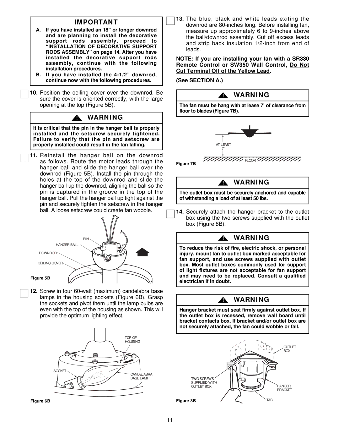
14.Securely attach the hanger bracket to the outlet box using the two screws supplied with the outlet box (Figure 8B).
!WARNING
To reduce the risk of fire, electric shock, or personal injury, mount fan to outlet box marked acceptable for fan support, and use screws supplied with outlet box. Most outlet boxes commonly used for support of light fixtures are not acceptable for fan support and may need to be replaced. Consult a qualified electrician if in doubt.
!WARNING
Hanger bracket must seat firmly against outlet box. If the outlet box is recessed, remove wall board until bracket contacts box. If bracket and/or outlet box are not securely attached, the fan could wobble or fall.
OUTLET
![]() BOX
BOX
TWO SCREWS |
|
SUPPLIED WITH | HANGER |
OUTLET BOX | |
| BRACKET |
Figure 8B | TAB |
11