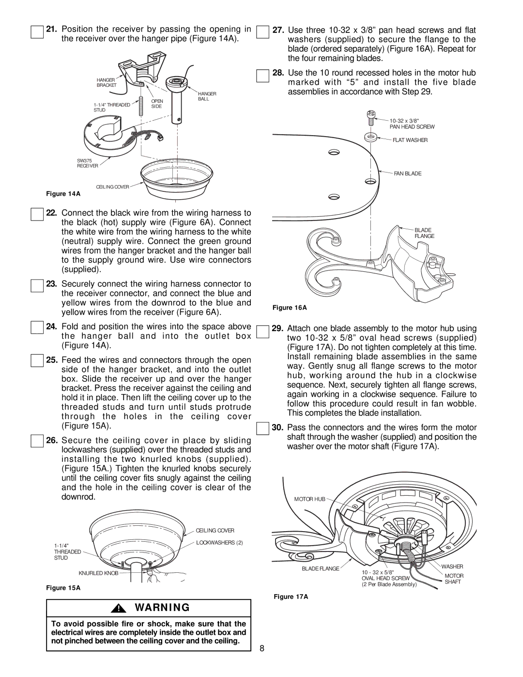
21.Position the receiver by passing the opening in the receiver over the hanger pipe (Figure 14A).
27. Use three |
washers (supplied) to secure the flange to the |
blade (ordered separately) (Figure 16A). Repeat for |
the four remaining blades. |
28. Use the 10 round recessed holes in the motor hub |
HANGER
BRACKET
OPEN
SW375
RECEIVER
CEILING COVER ![]()
Figure 14A
HANGER BALL
marked with “5” and install the | five blade |
assemblies in accordance with Step 29. |
|
![]()
PAN HEAD SCREW

 FLAT WASHER
 FAN BLADE
22.Connect the black wire from the wiring harness to the black (hot) supply wire (Figure 6A). Connect the white wire from the wiring harness to the white (neutral) supply wire. Connect the green ground wires from the hanger bracket and the hanger ball to the supply ground wire. Use wire connectors (supplied).
23.Securely connect the wiring harness connector to the receiver connector, and connect the blue and yellow wires from the downrod to the blue and yellow wires from the receiver (Figure 6A).
24.Fold and position the wires into the space above the hanger ball and into the outlet box (Figure 14A).
25.Feed the wires and connectors through the open side of the hanger bracket, and into the outlet box. Slide the receiver up and over the hanger bracket. Press the receiver against the ceiling and hold it in place. Then lift the ceiling cover up to the threaded studs and turn until studs protrude through the holes in the ceiling cover (Figure 15A).
26.Secure the ceiling cover in place by sliding lockwashers (supplied) over the threaded studs and installing the two knurled knobs (supplied). (Figure 15A.) Tighten the knurled knobs securely until the ceiling cover fits snugly against the ceiling and the hole in the ceiling cover is clear of the downrod.
![]() BLADE
BLADE
FLANGE
Figure 16A
29.Attach one blade assembly to the motor hub using two
30.Pass the connectors and the wires form the motor shaft through the washer (supplied) and position the washer over the motor shaft (Figure 17A).
MOTOR HUB
| CEILING COVER |
LOCKWASHERS (2) | |
| |
THREADED |
|
STUD |
|
KNURLED KNOB |
|
Figure 15A
!WARNING
To avoid possible fire or shock, make sure that the electrical wires are completely inside the outlet box and not pinched between the ceiling cover and the ceiling.
BLADE FLANGE | 10 - 32 x 5/8" | WASHER | |
MOTOR | |||
| |||
| OVAL HEAD SCREW | ||
| SHAFT | ||
| (2 Per Blade Assembly) | ||
|
|
Figure 17A
8