2.3 Control unit installation
The control units should be installed in an area suitable to their specifications. They are designed to be used indoors, but could be installed outside using a suitable weatherproof enclosure. The front panel should be accessible to the operator.
The standard control unit MEP*L is installed by undoing the two screws on the top and bottom of the unit, and removing the base. This can now be mounted as required, making sure that the connection terminals are on the
The 19” rack unit should be mounted in a suitable cabinet in the usual fashion. It accepts up to fourteen rack modules to type MEP*R. It should be noted that I.S. control units MEP3R will only fit into an I.S. rack MEP3B and that the rack is included in the approval. Mounting details are shown on the previous page.
Allow at least a 50mm gap between each rack on multiple rack installations to allow air circulation. On installations of
Wires to the MEP*B rack units are connected to the terminal blocks mounted on the rear panel of the rack. In the factory the modules are fitted starting from the left hand side when viewed from the front of the rack. If desirable, the connectors and modules can be repositioned in the rack. To assist with cable wiring, the connector block wire access faces the rear of the rack and the screw terminals are therefore angled. To fit cable to the 5 modules closest to the right hand end of the rack (numbers 10- 14) it is necessary to release the connector and rotate it slightly to allow screwdriver access.
2.4Wiring
i) Cable
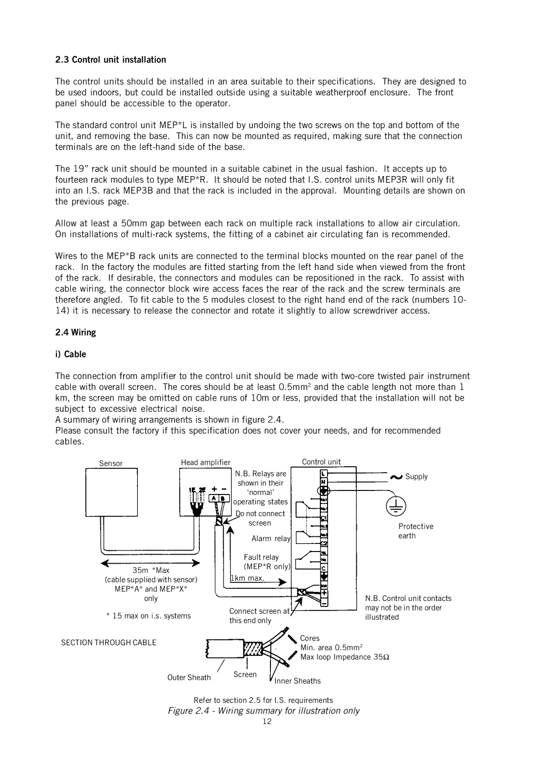
The connection from amplifier to the control unit should be made with
A summary of wiring arrangements is shown in figure 2.4.
Please consult the factory if this specification does not cover your needs, and for recommended cables.
Sensor | Head amplifier | |
|
| N.B. Relays are |
|
| shown in their |
|
| ‘normal’ |
|
| operating states |
|
| Do not connect |
|
| screen |
|
| Alarm relay |
|
| Fault relay |
| 35m *Max | (MEP*R only) |
| 1km max. | |
(cable supplied with sensor) | ||
MEP*A* and MEP*X* |
| |
| only |
|
Control unit
Supply
Protective earth
N.B. Control unit contacts may not be in the order
* 15 max on i.s. systems
SECTION THROUGH CABLE
Connect screen at this end only
illustrated
Cores
Min. area 0.5mm2
Max loop Impedance 35Ω
Outer Sheath | Screen | |
Inner Sheaths | ||
|
Refer to section 2.5 for I.S. requirements
Figure 2.4 - Wiring summary for illustration only
12