ii) Head Amplifier Unit
The head amplifier terminals A+ and B- should be connected to the cores of the control unit cable. In the case of the dual marine unit, lower sensor connections A+ and B- are connected to the two cores of one cable, and upper sensor connections, C- and D+ to the other. The screen should not be connected in any head amplifier unit, as this could cause an earth loop. The marine head amplifier has cable grips which should be used. Care should be taken not to overtighten these, as this could result in damage to the circuit board. The cable is then taken out through the cable entry in the head amplifier.
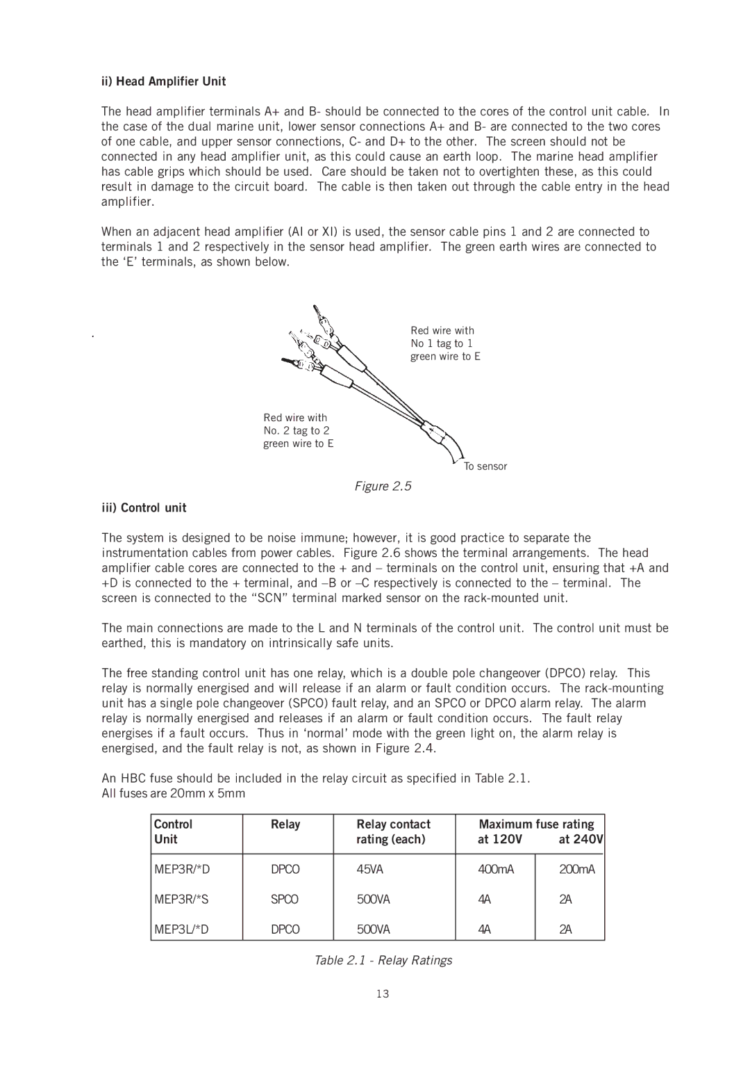
When an adjacent head amplifier (AI or XI) is used, the sensor cable pins 1 and 2 are connected to terminals 1 and 2 respectively in the sensor head amplifier. The green earth wires are connected to the ‘E’ terminals, as shown below.
.
Red wire with No. 2 tag to 2 green wire to E
Red wire with No 1 tag to 1 green wire to E
To sensor
Figure 2.5
iii) Control unit
The system is designed to be noise immune; however, it is good practice to separate the instrumentation cables from power cables. Figure 2.6 shows the terminal arrangements. The head amplifier cable cores are connected to the + and – terminals on the control unit, ensuring that +A and +D is connected to the + terminal, and
The main connections are made to the L and N terminals of the control unit. The control unit must be earthed, this is mandatory on intrinsically safe units.
The free standing control unit has one relay, which is a double pole changeover (DPCO) relay. This relay is normally energised and will release if an alarm or fault condition occurs. The
An HBC fuse should be included in the relay circuit as specified in Table 2.1. All fuses are 20mm x 5mm
Control | Relay |
| Relay contact | Maximum fuse rating | |
Unit |
|
| rating (each) | at 120V | at 240V |
|
|
|
|
|
|
MEP3R/*D | DPCO |
| 45VA | 400mA | 200mA |
MEP3R/*S | SPCO |
| 500VA | 4A | 2A |
MEP3L/*D | DPCO |
| 500VA | 4A | 2A |
|
|
|
|
|
|
|
| Table 2.1 - Relay Ratings |
|
| |
13