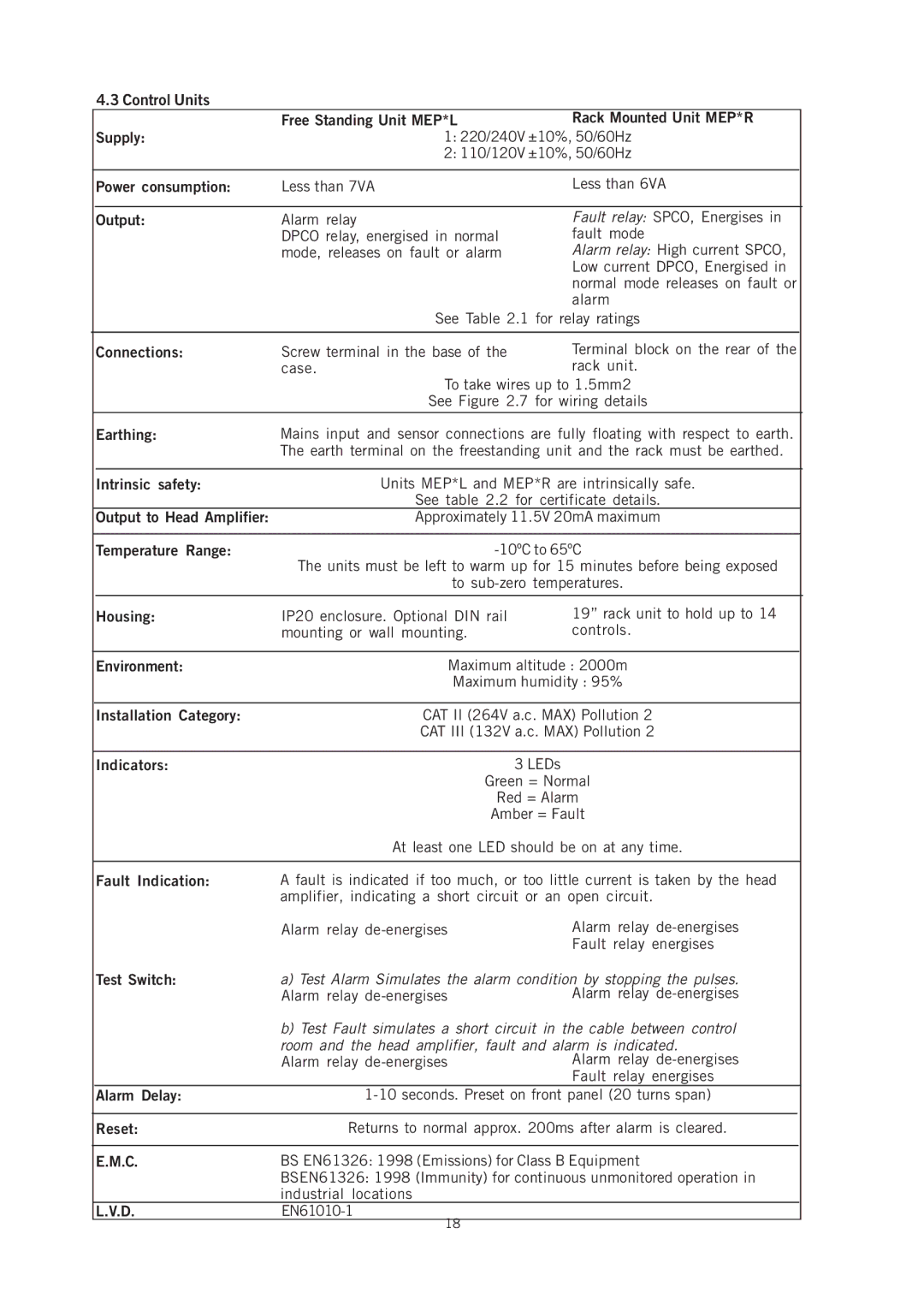
4.3 Control Units
|
| Free Standing Unit MEP*L | Rack Mounted Unit MEP*R |
|
| Supply: | 1: 220/240V ±10%, 50/60Hz |
| |
|
| 2: 110/120V ±10%, 50/60Hz |
| |
|
|
|
|
|
| Power consumption: | Less than 7VA | Less than 6VA |
|
|
|
|
|
|
| Output: | Alarm relay | Fault relay: SPCO, Energises in |
|
|
| DPCO relay, energised in normal | fault mode |
|
|
| mode, releases on fault or alarm | Alarm relay: High current SPCO, |
|
|
|
| Low current DPCO, Energised in |
|
|
|
| normal mode releases on fault or |
|
|
|
| alarm |
|
|
| See Table 2.1 for relay ratings |
| |
|
|
|
|
|
| Connections: | Screw terminal in the base of the | Terminal block on the rear of the |
|
|
| case. | rack unit. |
|
To take wires up to 1.5mm2
See Figure 2.7 for wiring details
| Earthing: | Mains input and sensor connections are fully floating with respect to earth. | ||
|
| The earth terminal on the freestanding unit and the rack must be earthed. | ||
|
|
|
| |
| Intrinsic safety: | Units MEP*L and MEP*R are intrinsically safe. | ||
|
| See table 2.2 for certificate details. | ||
| Output to Head Amplifier: | Approximately 11.5V 20mA maximum | ||
|
|
|
| |
| Temperature Range: | |||
|
| The units must be left to warm up for 15 minutes before being exposed | ||
|
| to | ||
|
|
|
|
|
| Housing: | IP20 enclosure. Optional DIN rail | 19” rack unit to hold up to 14 | |
|
| mounting or wall mounting. | controls. | |
|
|
|
| |
| Environment: | Maximum altitude : 2000m | ||
|
| Maximum humidity : 95% | ||
|
|
|
| |
| Installation Category: | CAT II (264V a.c. MAX) Pollution 2 | ||
|
| CAT III (132V a.c. MAX) Pollution 2 | ||
|
|
|
|
|
| Indicators: |
| 3 LEDs | |
|
| Green = Normal | ||
|
| Red = Alarm | ||
|
| Amber = Fault | ||
|
| At least one LED should be on at any time. | ||
|
|
|
| |
| Fault Indication: | A fault is indicated if too much, or too little current is taken by the head | ||
|
| amplifier, indicating a short circuit or an open circuit. | ||
|
| Alarm relay | Alarm relay | |
|
|
| Fault relay energises | |
| Test Switch: | a) Test Alarm Simulates the alarm condition by stopping the pulses. | ||
|
| Alarm relay | Alarm relay | |
|
| b) Test Fault simulates a short circuit in the cable between control | ||
|
| room and the head amplifier, fault and alarm is indicated. | ||
|
| Alarm relay | Alarm relay | |
|
|
| Fault relay energises | |
| Alarm Delay: | |||
|
|
|
| |
| Reset: | Returns to normal approx. 200ms after alarm is cleared. | ||
|
|
|
| |
| E.M.C. | BS EN61326: 1998 (Emissions) for Class B Equipment | ||
|
| BSEN61326: 1998 (Immunity) for continuous unmonitored operation in | ||
|
| industrial locations |
|
|
| L.V.D. |
|
| |
18
