2.2 Sensor and head amplifier installation
Make sure that there is room inside the tank for the sensor without anything touching it, and that the gap is not obstructed. At least an inch of clearance must be left around
For threaded sensors a hole is drilled in the tank at the appropriate level, and this is tapped to take the sensor. On thin walled tanks it may be necessary to fit a boss to the tank. Use PTFE tape or similar to seal the thread so that the sensor does not have to be
For flanged sensors, arrange a suitable counter flange, and fit using a gasket, tightening the bolts evenly. If possible the bridge of sensors 302S and 402S should be to the side of the gap, and not above or below it, and all gap sensors should have their gaps vertical. This is so that any sludge in the tank cannot settle on the faces of the sensor.
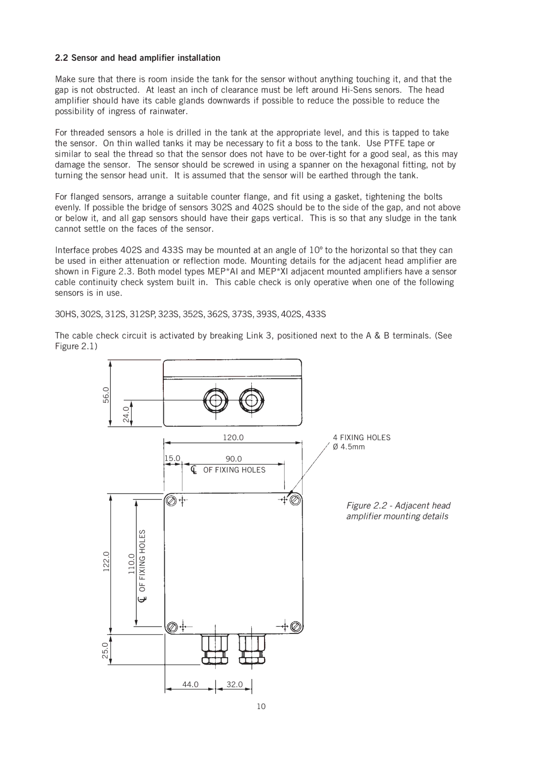
Interface probes 402S and 433S may be mounted at an angle of 10º to the horizontal so that they can be used in either attenuation or reflection mode. Mounting details for the adjacent head amplifier are shown in Figure 2.3. Both model types MEP*AI and MEP*XI adjacent mounted amplifiers have a sensor cable continuity check system built in. This cable check is only operative when one of the following sensors is in use.
30HS, 302S, 312S, 312SP, 323S, 352S, 362S, 373S, 393S, 402S, 433S
The cable check circuit is activated by breaking Link 3, positioned next to the A & B terminals. (See Figure 2.1)
56.0 24.0
| 120.0 | 4 FIXING HOLES |
|
| Ø 4.5mm |
15.0 | 90.0 |
|
| OF FIXING HOLES |
|
Figure 2.2 - Adjacent head amplifier mounting details
122.0 | 110.0 | FIXING HOLES |
|
| OF |
25.0
44.032.0
10