2.Installation 2.1 Calibration
When installing the sensor, it should be remembered that it is measuring instrument, and should be treated with care. Before installation the sensor and control unit should be inspected for transit damage, the gap faces of gap sensors must be parallel. Before installation, the equipment should be calibrated, if possible, using a representative sample of the liquid in which it is to be used. The head amplifier unit should be wired to the control unit, which should be connected to its power supply. Wiring instructions are given in section 2.4.
When the mains supply to the control unit is switched on, either the green ‘normal’ light or the red ‘alarm’ light should be on, the amber ‘fault’ light should be off. The lid of the head amplifier unit is removed by undoing the four screws or Allen bolts. Care should be taken not to damage the sealing gasket, which should be replaced with the lid. When using integral head amplifiers, the sensor must not be unscrewed from the head amplifier unit as this is likely to damage the internal wiring (and may violate ATEX approval).
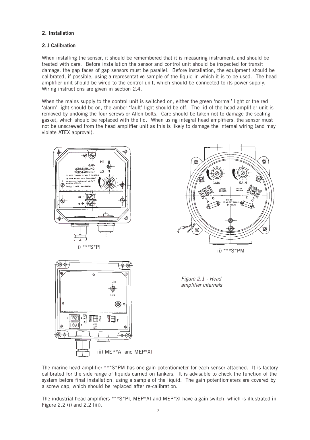
i) ***S*PI
ii) ***S*PM
Figure 2.1 - Head amplifier internals
iii) MEP*AI and MEP*XI
The marine head amplifier ***S*PM has one gain potentiometer for each sensor attached. It is factory calibrated for the side range of liquids carried on tankers. It is advisable to check the function of the system before final installation, using a sample of the liquid. The gain potentiometers are covered by a screw cap, which should be replaced after
The industrial head amplifiers ***S*PI, MEP*AI and MEP*XI have a gain switch, which is illustrated in Figure 2.2 (i) and 2.2 (iii).
7