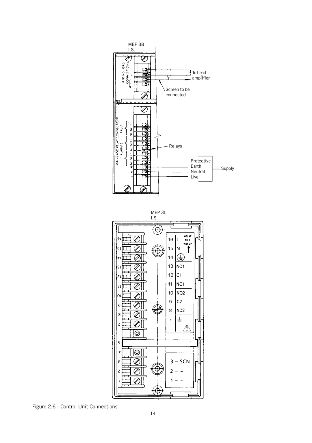
Manuals
/
Brands
/
Fitness & Sports
/
Fitness Electronics
/
Emerson
/
Fitness & Sports
/
Fitness Electronics
Emerson
IP221
Figure 2.6 - Control Unit Connections
1
14
24
24
Download
24 pages, 271.59 Kb
14
Figure 2.6 - Control Unit Connections
MEP 3L
I.S.
Relays
Screen to be
connected
To head
amplifier
MEP 3B
I.S.
Protective
Earth
Neutral
Live
Supply
Contents
Main
www.mobrey.com
Instructions Leaflet
IP221, Rev. AA November 2004
Mobrey
Level
Electropulse systems
!
Figure 1.1 - Gap sensor, cut away to show construction
Figure 1.2 - Hi-Sens, cut- away to show construction
Figure 1.3 - Attenuation Method
Figure 1.4
(a) Clear liquid, signal transmitted (b) Solids attenuate the signal
Figure 1.5 - Sludge density sensor, operation
i) Normal acting head amplifiers
ii) Inverse acting head amplifiers
Figure 2.1 - Head amplifier internals
Page
Page
Figure 2.2 - Adjacent head amplifier mounting details
Page
Figure 2.4 - Wiring summary for illustration only
Figure 2.5
Table 2.1 - Relay Ratings
Figure 2.6 - Control Unit Connections
Certificates of Conformity
Table 2.2 - Approvals
Page
Table 4.1 - Sensor specification
4.3 Control Units
Fault relay:
Alarm relay:
Standard Control Unit:
Rack Mounted Unit:
3 0 2 S D P 8 0 T
M E P 3 A I / 3 C A N
}
Industrial Only
M E P 3 L / 1 D
M E P 3 B / 0 7
Page
Page
abcdef
Instructions Leaflet
IP221, Rev. AA November 2004 Level