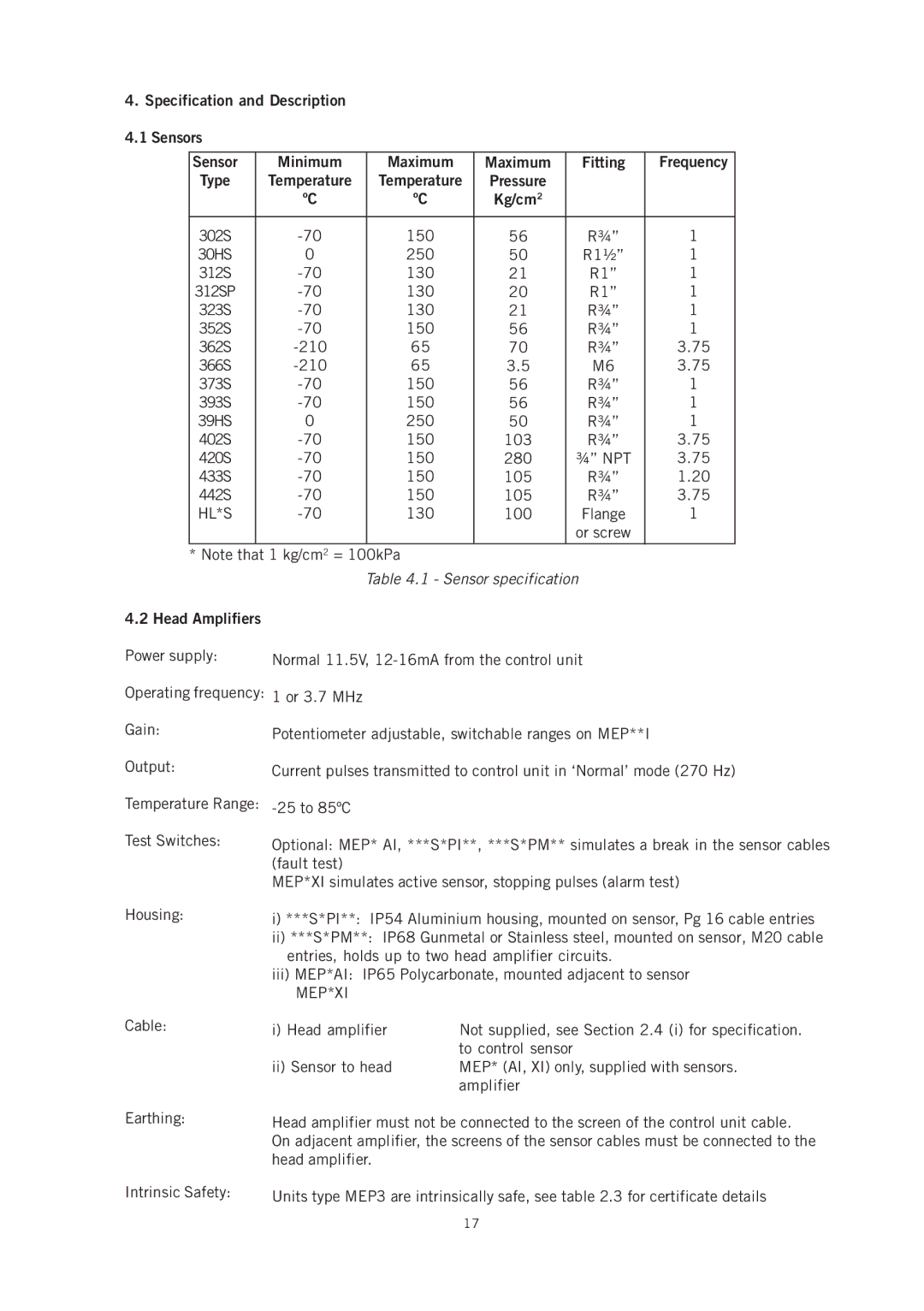
4.Specification and Description 4.1 Sensors
Sensor | Minimum | Maximum | Maximum | Fitting | Frequency |
Type | Temperature | Temperature | Pressure |
|
|
| ºC | ºC | Kg/cm2 |
|
|
|
|
|
|
|
|
302S | 150 | 56 | R¾” | 1 | |
30HS | 0 | 250 | 50 | R1½” | 1 |
312S | 130 | 21 | R1” | 1 | |
312SP | 130 | 20 | R1” | 1 | |
323S | 130 | 21 | R¾” | 1 | |
352S | 150 | 56 | R¾” | 1 | |
362S | 65 | 70 | R¾” | 3.75 | |
366S | 65 | 3.5 | M6 | 3.75 | |
373S | 150 | 56 | R¾” | 1 | |
393S | 150 | 56 | R¾” | 1 | |
39HS | 0 | 250 | 50 | R¾” | 1 |
402S | 150 | 103 | R¾” | 3.75 | |
420S | 150 | 280 | ¾” NPT | 3.75 | |
433S | 150 | 105 | R¾” | 1.20 | |
442S | 150 | 105 | R¾” | 3.75 | |
HL*S | 130 | 100 | Flange | 1 | |
|
|
|
| or screw |
|
* Note that 1 kg/cm2 = 100kPa
Table 4.1 - Sensor specification
4.2 Head Amplifiers
Power supply:
Operating frequency:
Gain:
Output:
Temperature Range:
Test Switches:
Normal 11.5V,
1 or 3.7 MHz
Potentiometer adjustable, switchable ranges on MEP**I
Current pulses transmitted to control unit in ‘Normal’ mode (270 Hz)
Optional: MEP* AI, ***S*PI**, ***S*PM** simulates a break in the sensor cables (fault test)
MEP*XI simulates active sensor, stopping pulses (alarm test)
Housing: | i) ***S*PI**: IP54 Aluminium housing, mounted on sensor, Pg 16 cable entries | |
| ii) ***S*PM**: IP68 Gunmetal or Stainless steel, mounted on sensor, M20 cable | |
| entries, holds up to two head amplifier circuits. | |
| iii) MEP*AI: IP65 Polycarbonate, mounted adjacent to sensor | |
| MEP*XI |
|
Cable: | i) Head amplifier | Not supplied, see Section 2.4 (i) for specification. |
|
| to control sensor |
| ii) Sensor to head | MEP* (AI, XI) only, supplied with sensors. |
|
| amplifier |
Earthing: | Head amplifier must not be connected to the screen of the control unit cable. | |
| On adjacent amplifier, the screens of the sensor cables must be connected to the | |
| head amplifier. |
|
Intrinsic Safety: | Units type MEP3 are intrinsically safe, see table 2.3 for certificate details | |
17