Z8 Encore!® Flash Microcontroller Development Kit
User Manual
•
•Voltage Brownout (VBO) Protection
•
•3.0
•0
For further information on the Z8 Encore! family of devices, refer to
Z8 Encore! XP® 64K Series Flash Microcontrollers Product Specification (PS0199).
LED Array
14
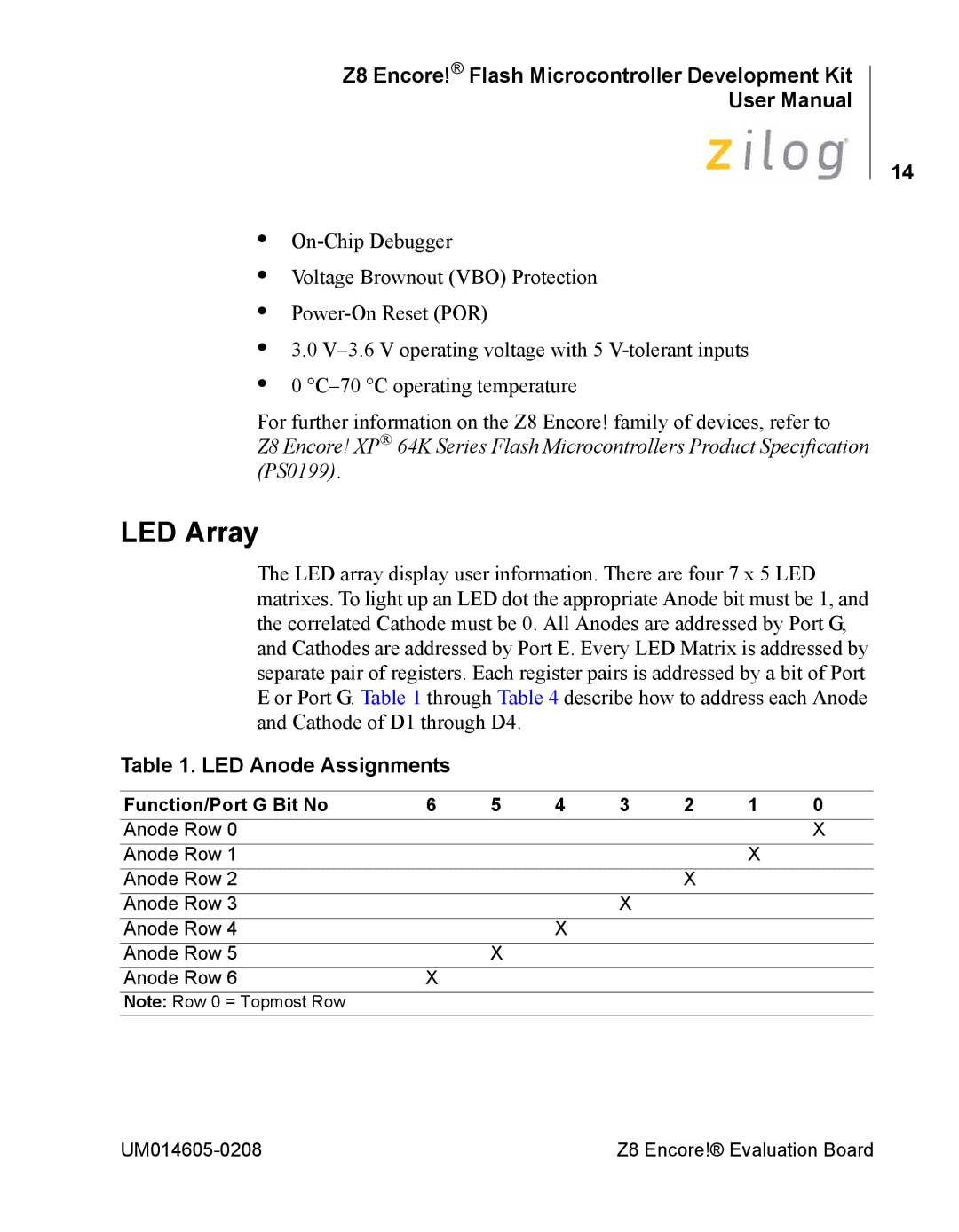
The LED array display user information. There are four 7 x 5 LED matrixes. To light up an LED dot the appropriate Anode bit must be 1, and the correlated Cathode must be 0. All Anodes are addressed by Port G, and Cathodes are addressed by Port E. Every LED Matrix is addressed by separate pair of registers. Each register pairs is addressed by a bit of Port E or Port G. Table 1 through Table 4 describe how to address each Anode and Cathode of D1 through D4.
Table 1. LED Anode Assignments
Function/Port G Bit No | 6 | 5 | 4 | 3 | 2 | 1 | 0 |
Anode Row 0 |
|
|
|
|
|
| X |
Anode Row 1 |
|
|
|
|
| X |
|
Anode Row 2 |
|
|
|
| X |
|
|
Anode Row 3 |
|
|
| X |
|
|
|
Anode Row 4 |
|
| X |
|
|
|
|
Anode Row 5 |
| X |
|
|
|
|
|
Anode Row 6 | X |
|
|
|
|
|
|
Note: Row 0 = Topmost Row |
|
|
|
|
|
|
|
Z8 Encore!® Evaluation Board |