Maintenance And Service
REPLACING THE GLASS:
IMPORTANT: Do not operate with the glass front removed, cracked or broken. The glass in the fireplace is a high temperature ceramic. If the glass is damaged in any way, a factory replacement door is required (see PARTS LIST). Wear gloves when handling the damaged glass door assembly to prevent personal injury. When the glass door assembly is being transported, it must be wrapped in newsprint and tape and/or a strong plastic bag. Removal and replacement of the glass from the door must be done by a licensed or qualified service person. The door assembly must be purchased from an ENVIRO dealer.
No substitute materials are allowed.
CLEANING THE FIREBOX:
With the fireplace at room temperature, carefully remove the logs. Gently remove the ceramic burner and place on a paper towel. Vacuum the bottom of the firebox thoroughly. Carefully clean any dust off the logs and remove any lint from the burner and pilot. At this time, inspect the burner pan for cracking or severe warping. If a problem is suspected, contact the dealer. Check the logs for deterioration or large amounts of soot; a small amount on the bottom side of the logs is normal. Replace the logs as in the LOG
SET INSTALLATION section.
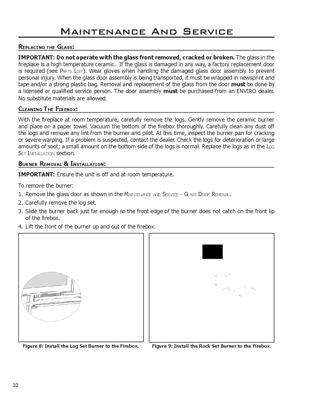
BURNER REMOVAL & INSTALLATION:
IMPORTANT: Ensure the unit is off and at room temperature.
To remove the burner:
1.Remove the glass door as shown in the MAINTENANCE AND SERVICE - GLASS DOOR REMOVAL.
2.Carefully remove the log set.
3.Slide the burner back just far enough so the front edge of the burner does not catch on the front lip
of the firebox.
4. Lift the front of the burner up and out of the firebox.
|
|
|
Figure 8: Install the Log Set Burner to the Firebox. | Figure 9: Install the Rock Set Burner to the Firebox. | |
10