Initial Installation
QUALIFIED INSTALLERS ONLY
the outside, on black pipe. They may be located by examining the inside of the female ends as shown in Figure 31.
Notes:
(a)
(b)Horizontal runs of vent pipe must be supported every 36” (915mm). Wall straps are available for this purpose, also when running horizontal pipe minimum clearances to combustibles must be maintained;
2” (51mm) at top, 11⁄2” (38mm) at sides, 11⁄2” (38mm) at bottom.
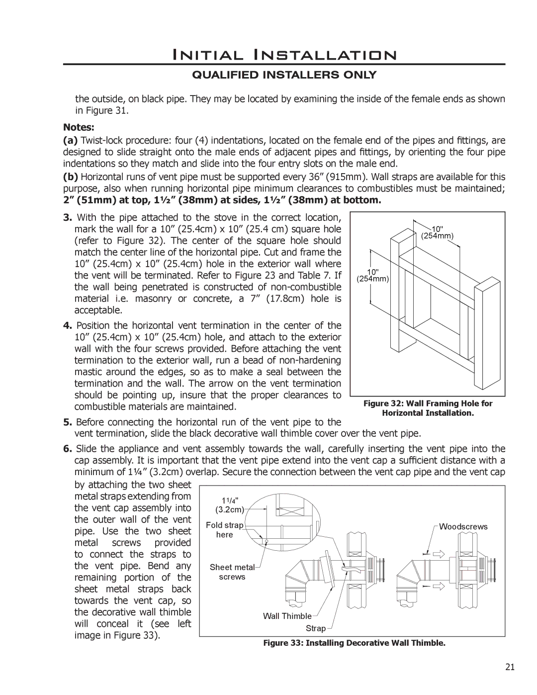
3. With the pipe attached to the stove in the correct location, |
|
|
|
|
|
|
|
|
|
|
|
|
| |
|
|
|
|
|
|
|
|
|
|
|
|
| ||
mark the wall for a 10” (25.4cm) x 10” (25.4 cm) square hole |
|
| 10" |
|
|
|
|
| ||||||
(refer to Figure 32). The center of the square hole should |
|
|
|
|
|
| (254mm) | |||||||
|
|
|
|
|
|
|
|
|
|
|
|
| ||
match the center line of the horizontal pipe. Cut and frame the |
|
|
|
|
|
|
|
|
|
|
|
|
| |
|
|
|
|
|
|
|
|
|
|
|
|
| ||
10” (25.4cm) x 10” (25.4cm) hole in the exterior wall where |
|
|
|
|
|
|
|
|
|
|
|
|
| |
the vent will be terminated. Refer to Figure 23 and Table 7. If | 10" |
|
|
|
|
|
|
|
|
|
|
| ||
|
|
|
|
|
|
|
|
| ||||||
|
|
|
|
|
|
|
|
|
|
| ||||
the wall being penetrated is constructed of | (254mm) |
|
|
|
|
|
|
|
|
|
| |||
|
|
|
|
|
|
|
|
|
|
| ||||
|
|
|
|
|
|
|
|
|
|
|
|
| ||
|
|
|
|
|
|
|
|
|
|
|
|
| ||
material i.e. masonry or concrete, a 7” (17.8cm) hole is |
|
|
|
|
|
|
|
|
|
|
|
|
| |
|
|
|
|
|
|
|
|
|
|
|
|
| ||
acceptable. |
|
|
|
|
|
|
|
|
|
|
|
|
| |
|
|
|
|
|
|
|
|
|
|
|
|
| ||
4. Position the horizontal vent termination in the center of the |
|
|
|
|
|
|
|
|
|
|
|
|
| |
|
|
|
|
|
|
|
|
|
|
|
|
| ||
|
|
|
|
|
|
|
|
|
|
|
|
| ||
|
|
|
|
|
|
|
|
|
|
|
|
| ||
10” (25.4cm) x 10” (25.4cm) hole, and attach to the exterior |
|
|
|
|
|
|
|
|
|
|
|
|
| |
|
|
|
|
|
|
|
|
|
|
|
|
| ||
wall with the four screws provided. Before attaching the vent |
|
|
|
|
|
|
|
|
|
|
|
|
| |
|
|
|
|
|
|
|
|
|
|
|
|
| ||
termination to the exterior wall, run a bead of |
|
|
|
|
|
|
|
|
|
|
|
|
| |
|
|
|
|
|
|
|
|
|
|
|
|
| ||
|
|
|
|
|
|
|
|
|
|
|
|
| ||
mastic around the edges, so as to make a seal between the |
|
|
|
|
|
|
|
|
|
|
|
|
| |
termination and the wall. The arrow on the vent termination |
|
|
|
|
|
|
|
|
|
|
|
|
| |
|
|
|
|
|
|
|
|
|
|
|
|
| ||
|
|
|
|
|
|
|
|
|
|
|
|
| ||
should be pointing up, insure that the proper clearances to |
|
|
|
|
|
|
|
|
|
|
|
|
| |
Figure 32: Wall Framing Hole for | ||||||||||||||
combustible materials are maintained. | ||||||||||||||
5. Before connecting the horizontal run of the vent pipe to the |
| Horizontal Installation. | ||||||||||||
|
|
|
|
|
|
|
|
|
|
|
|
| ||
vent termination, slide the black decorative wall thimble cover over the vent pipe.
6.Slide the appliance and vent assembly towards the wall, carefully inserting the vent pipe into the cap assembly. It is important that the vent pipe extend into the vent cap a sufficient distance with a minimum of 11⁄4” (3.2cm) overlap. Secure the connection between the vent cap pipe and the vent cap
by attaching the two sheet metal straps extending from the vent cap assembly into the outer wall of the vent pipe. Use the two sheet metal screws provided to connect the straps to the vent pipe. Bend any remaining portion of the sheet metal straps back towards the vent cap, so the decorative wall thimble will conceal it (see left image in Figure 33).
11/4" |
|
(3.2cm) |
|
Fold strap | Woodscrews |
here |
|
Sheet metal |
|
screws |
|
| Wall Thimble |
| Strap |
Figure 33: Installing Decorative Wall Thimble.
21