Initial Installation
QUALIFIED INSTALLERS ONLY
RESTRICTOR INSTALLATION:
The ENVIRO CARA has been designed for use with an
1.Choose the appropriate restrictor for the installation (see INITIAL INSTALLATION - VENT CONFIGURATIONS AND RESTRICTOR SETTINGS). To avoid injury, install the restrictor when the fireplace is cool or use welder’s gloves or oven mitts.
2.Remove the glass door (see MAINTENANCE AND SERVICE - GLASS DOOR REMOVAL) and the firebox baffle (seE
MAINTENANCE AND SERVICE - FIREBOX BAFFLE REMOVAL).
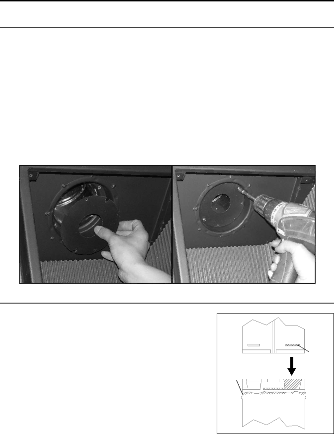
3.Remove two (2) 1⁄4” hex head screws for the restrictor, place restrictor in the flue collar (see Figure 30) and fasten in place with the two (2) 1⁄4” hex head screws.
4.
5.Wait for the unit to warm up to operating temperature to ensure a proper and clean burning unit.
Figure 30: Flue Restrictor Installation.
HORIZONTAL INSTALLATION:
1.Set the appliance in the desired location. Check to determine if wall studs or roof rafters are in the way when the venting system is attached. If this is the case, you may want to adjust the location of the appliance.
2.Direct vent pipe and fittings are designed with special
Place a bead of
Female |
Locking |
Lugs |
Sealant
![]()
![]() Male
Male
![]()
![]()
![]()
![]()
![]()
![]()
![]()
![]() Locking
Locking
Lugs
Figure 31: Twist-Lock Connection.
20
