Initial Installation
QUALIFIED INSTALLERS ONLY
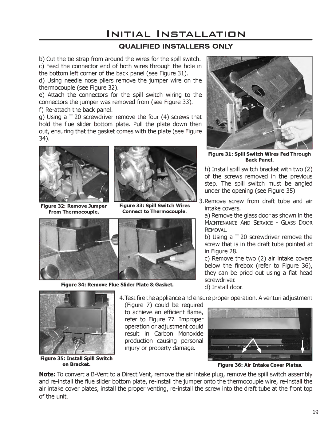
b)Cut the tie strap from around the wires for the spill switch.
c)Feed the connector end of both wires through the hole in the bottom left corner of the back panel (see Figure 31).
d)Using needle nose pliers remove the jumper wire on the thermocouple (see Figure 32).
e)Attach the connectors for the spill switch wiring to the connectors the jumper was removed from (see Figure 33).
f)
g)Using a
|
|
|
|
|
Figure 32: Remove Jumper |
| Figure 33: Spill Switch Wires |
| |
From Thermocouple. |
| Connect to Thermocouple. |
| |
|
|
|
|
|
|
|
|
|
|
Figure 34: Remove Flue Slider Plate & Gasket.
Figure 31: Spill Switch Wires Fed Through
Back Panel.
h)Install spill switch bracket with two (2) of the screws removed in the previous step. The spill switch must be angled under the opening (see Figure 35)
3.Remove screw from draft tube and air intake covers.
a)Remove the glass door as shown in the
MAINTENANCE AND SERVICE - GLASS DOOR
REMOVAL.
b)Using a
c)Remove the two (2) air intake covers below the firebox (refer to Figure 36), they can be pried out using a flat head screwdriver.
d)Install door.
Figure 35: Install Spill Switch
on Bracket.
4.Test fire the appliance and ensure proper operation. A venturi adjustment (Figure 7) could be required
to achieve an efficient flame, refer to Figure 77. Improper operation or adjustment could result in Carbon Monoxide production causing personal injury or property damage.
Figure 36: Air Intake Cover Plates.
Note: To convert a
of the unit.
19
