Initial Installation
QUALIFIED INSTALLERS ONLY
|
|
|
|
| Figure 55: Opening Inlet Pressure Tap on |
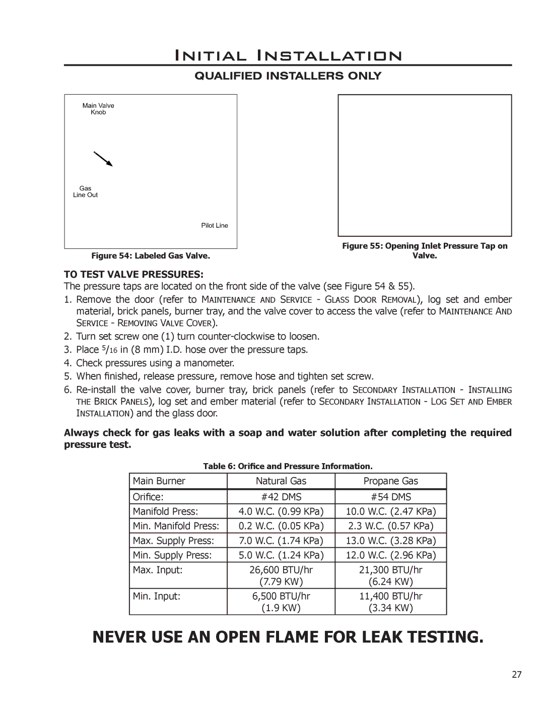
Figure 54: Labeled Gas Valve. |
| Valve. |
TO TEST VALVE PRESSURES:
The pressure taps are located on the front side of the valve (see Figure 54 & 55).
1.Remove the door (refer to MAINTENANCE AND SERVICE - GLASS DOOR REMOVAL), log set and ember material, brick panels, burner tray, and the valve cover to access the valve (refer to MAINTENANCE AND
SERVICE - REMOVING VALVE COVER).
2.Turn set screw one (1) turn
3.Place 5/16 in (8 mm) I.D. hose over the pressure taps.
4.Check pressures using a manometer.
5.When finished, release pressure, remove hose and tighten set screw.
6.
THE BRICK PANELS), log set and ember material (refer to SECONDARY INSTALLATION - LOG SET AND EMBER
INSTALLATION) and the glass door.
Always check for gas leaks with a soap and water solution after completing the required pressure test.
Table 6: Orifice and Pressure Information.
Main Burner | Natural Gas | Propane Gas |
|
|
|
Orifice: | #42 DMS | #54 DMS |
|
|
|
Manifold Press: | 4.0 W.C. (0.99 KPa) | 10.0 W.C. (2.47 KPa) |
|
|
|
Min. Manifold Press: | 0.2 W.C. (0.05 KPa) | 2.3 W.C. (0.57 KPa) |
|
|
|
Max. Supply Press: | 7.0 W.C. (1.74 KPa) | 13.0 W.C. (3.28 KPa) |
|
|
|
Min. Supply Press: | 5.0 W.C. (1.24 KPa) | 12.0 W.C. (2.96 KPa) |
Max. Input: | 26,600 BTU/hr | 21,300 BTU/hr |
| (7.79 KW) | (6.24 KW) |
|
|
|
Min. Input: | 6,500 BTU/hr | 11,400 BTU/hr |
| (1.9 KW) | (3.34 KW) |
|
|
|
NEVER USE AN OPEN FLAME FOR LEAK TESTING.
27