ENVISION RESIDENTIAL INSTALLATION MANUAL
Closed Loop Ground Source Systems
Note: For closed loop systems with antifreeze protection, set
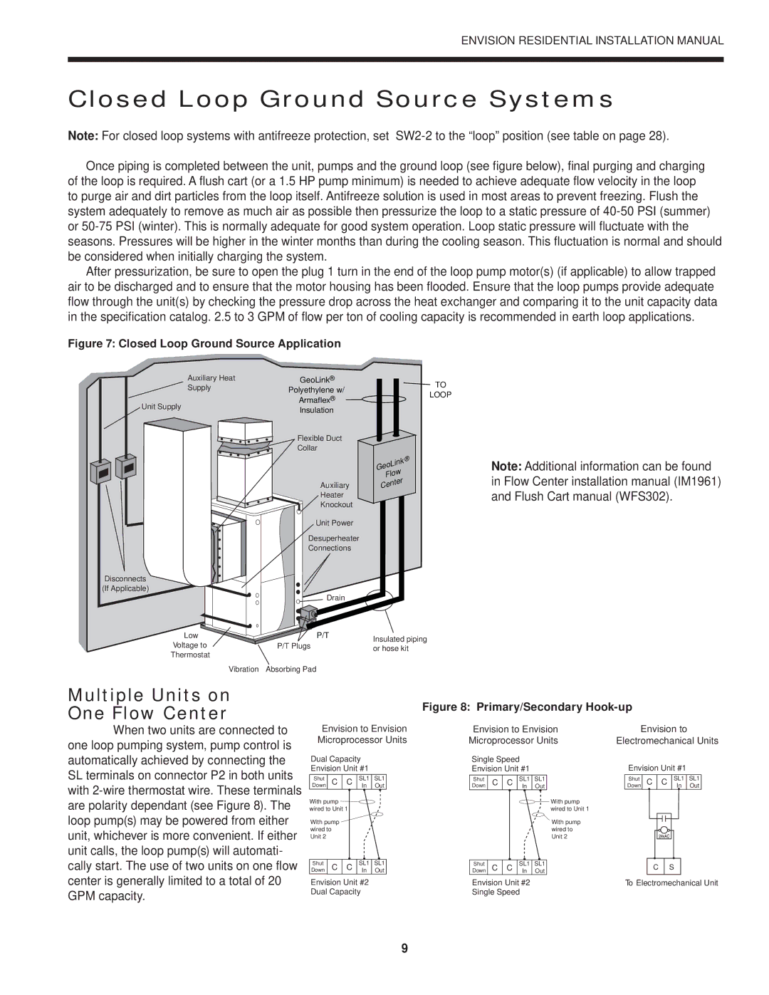
Once piping is completed between the unit, pumps and the ground loop (see figure below), final purging and charging of the loop is required. A flush cart (or a 1.5 HP pump minimum) is needed to achieve adequate flow velocity in the loop to purge air and dirt particles from the loop itself. Antifreeze solution is used in most areas to prevent freezing. Flush the system adequately to remove as much air as possible then pressurize the loop to a static pressure of
After pressurization, be sure to open the plug 1 turn in the end of the loop pump motor(s) (if applicable) to allow trapped air to be discharged and to ensure that the motor housing has been flooded. Ensure that the loop pumps provide adequate flow through the unit(s) by checking the pressure drop across the heat exchanger and comparing it to the unit capacity data in the specification catalog. 2.5 to 3 GPM of flow per ton of cooling capacity is recommended in earth loop applications.
Figure 7: Closed Loop Ground Source Application
Auxiliary Heat | GeoLink® | |
Supply | Polyethylene w/ | |
| ||
Unit Supply | Armaflex® | |
Insulation | ||
| ||
| Flexible Duct | |
| Collar | |
| Auxiliary | |
| Heater | |
| Knockout | |
| Unit Power | |
| Desuperheater | |
| Connections |
Disconnects
(If Applicable)
Drain
Low | P/T |
Voltage to | P/T Plugs |
Thermostat |
|
Vibration | Absorbing Pad |
TO
LOOP
| oLink | ® | |
Ge |
| ||
Flow |
| ||
Cent | er |
| |
|
| ||
Insulated piping or hose kit
Note: Additional information can be found in Flow Center installation manual (IM1961) and Flush Cart manual (WFS302).
Multiple Units on
One Flow Center
When two units are connected to one loop pumping system, pump control is
Figure 8: Primary/Secondary Hook-up
Envision to Envision | Envision to Envision | Envision to |
Microprocessor Units | Microprocessor Units | Electromechanical Units |
automatically achieved by connecting the SL terminals on connector P2 in both units with
Dual Capacity Envision Unit #1
Shut | C | C | SL1 | SL1 | |
Down |
|
|
| In | Out |
With pump |
|
|
|
| |
wired to Unit 1 |
|
|
| ||
With pump |
|
|
|
| |
wired to |
|
|
|
|
|
Unit 2 |
|
|
|
|
|
|
|
|
|
|
|
Shut | C | C | SL1 | SL1 | |
Down | In | Out | |||
Envision Unit #2 Dual Capacity
Single Speed
Envision Unit #1
Shut | C | C | SL1 | SL1 |
Down |
|
| In | Out |
With pump wired to Unit 1
With pump wired to Unit 2
Shut | C | C | SL1 | SL1 |
Down | In | Out |
Envision Unit #2
Single Speed
Envision Unit #1
Shut | C | C | SL1 | SL1 | ||
Down |
|
|
|
| In | Out |
|
|
|
|
|
|
|
|
|
|
|
|
|
|
|
|
|
|
|
|
|
|
|
|
|
|
|
|
|
|
|
|
|
|
|
C S
To Electromechanical Unit
9