ENVISION RESIDENTIAL INSTALLATION MANUAL
Electrical Connections (cont.)
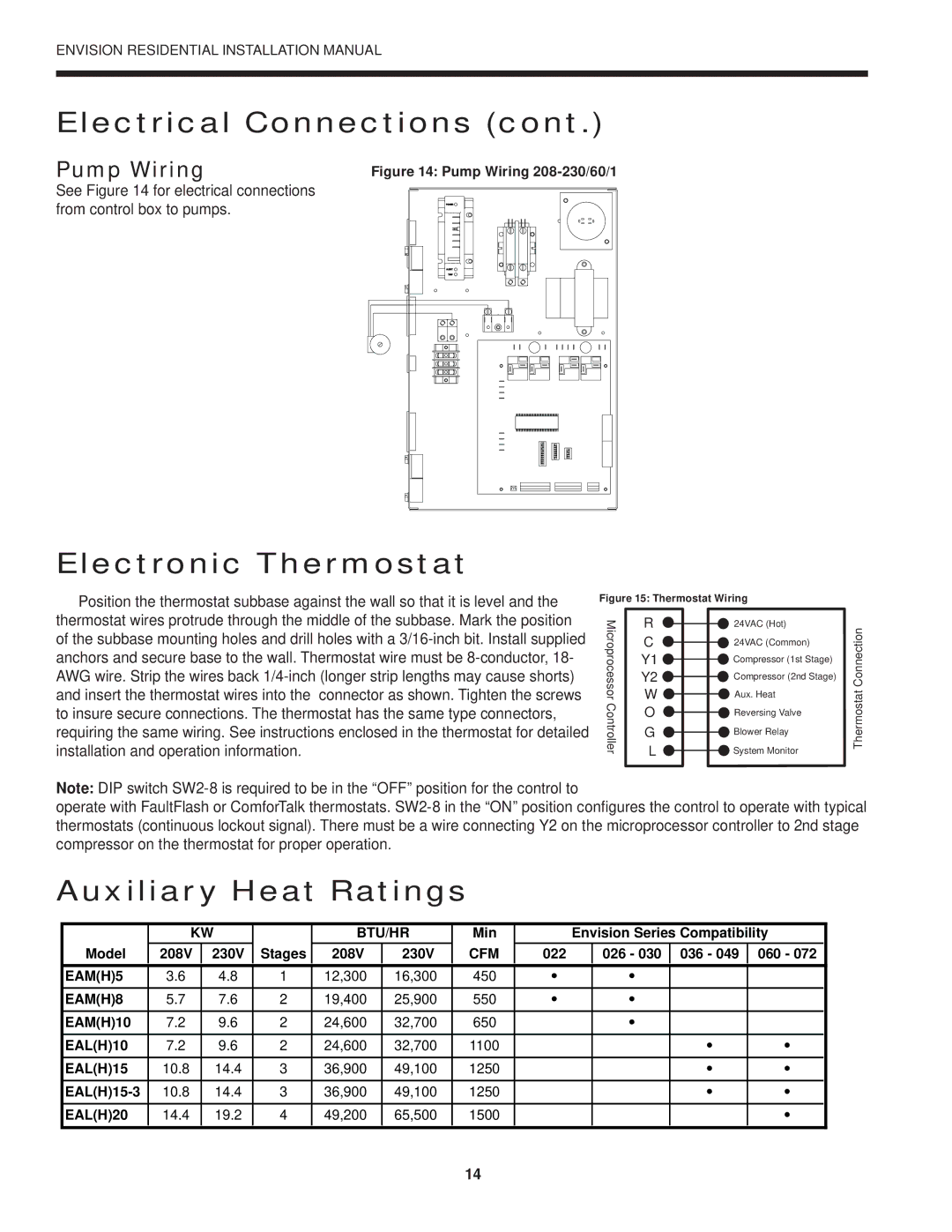
Pump Wiring
Figure 14: Pump Wiring 208-230/60/1
See Figure 14 for electrical connections from control box to pumps.
Electronic Thermostat
Position the thermostat subbase against the wall so that it is level and the thermostat wires protrude through the middle of the subbase. Mark the position of the subbase mounting holes and drill holes with a
Figure 15: Thermostat Wiring
Microprocessor | R |
|
| 24VAC (Hot) | |
|
| ||||
W |
| Aux. Heat | |||
| C |
|
| 24VAC (Common) | |
| Y1 |
|
| Compressor (1st Stage) | |
Controller | Y2 |
|
| Compressor (2nd Stage) | |
|
| ||||
|
|
|
|
| |
L |
| System Monitor | |||
| O |
|
| Reversing Valve | |
| G |
|
| Blower Relay | |
|
|
|
|
|
|
|
|
|
|
|
|
Thermostat Connection
Note: DIP switch
operate with FaultFlash or ComforTalk thermostats.
Auxiliary Heat Ratings
| KW |
| BTU/HR | Min |
| Envision Series Compatibility | ||||||
|
|
|
|
|
|
|
|
|
|
|
|
|
Model | 208V | 230V | Stages | 208V | 230V | CFM | 022 |
| 026 - 030 | 036 - 049 | 060 - 072 |
|
|
|
|
|
|
|
|
|
|
|
|
|
|
EAM(H)5 | 3.6 | 4.8 | 1 | 12,300 | 16,300 | 450 | • |
| • |
|
|
|
EAM(H)8 | 5.7 | 7.6 | 2 | 19,400 | 25,900 | 550 | • |
| • |
|
|
|
EAM(H)10 | 7.2 | 9.6 | 2 | 24,600 | 32,700 | 650 |
|
| • |
|
|
|
EAL(H)10 | 7.2 | 9.6 | 2 | 24,600 | 32,700 | 1100 |
|
|
| • | • |
|
EAL(H)15 | 10.8 | 14.4 | 3 | 36,900 | 49,100 | 1250 |
|
|
| • | • |
|
10.8 | 14.4 | 3 | 36,900 | 49,100 | 1250 |
|
|
| • | • |
| |
EAL(H)20 | 14.4 | 19.2 | 4 | 49,200 | 65,500 | 1500 |
|
|
|
| • |
|
14
