ENVISION RESIDENTIAL INSTALLATION MANUAL
Open Loop Ground Water Systems
Typical open loop piping is shown below. Always maintain water pressure in the heat exchanger by placing water control valves at the outlet of the unit to prevent mineral precipitation. Use a closed,
Discharge water from the unit is not contaminated in any manner and can be disposed of in various ways, depending on local codes, i.e. recharge well, storm sewer, drain field, adjacent stream or pond, etc. Most local codes forbid the use of sanitary sewer for disposal. Consult your local building and zoning departments to assure compliance in your area.
Note: For open loop/groundwater systems or systems that do not contain an antifreeze solution, set
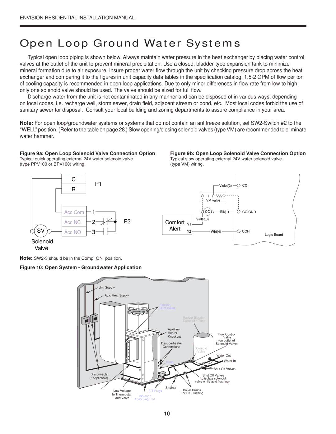
Figure 9a: Open Loop Solenoid Valve Connection Option
Typical quick operating external 24V water solenoid valve (type PPV100 or BPV100) wiring.
Figure 9b: Open Loop Solenoid Valve Connection Option
Typical slow operating external 24V water solenoid valve (type VM) wiring.
C
R
P1
Violet(2) ![]() CC
CC
VM valve
![]() SV
SV ![]()
Solenoid
Valve
Acc Com
Acc NC
Acc NO
1
2![]()
![]() P3
P3
3
Comfort Y1 Alert Y2
![]() CC
CC ![]() Blk(1)
Blk(1) ![]()
Violet(3)
Wht(4)CCHI
Logic Board
Note:
Figure 10: Open System - Groundwater Application
Unit Supply |
| |
Aux. Heat Supply |
| |
Flexible |
| |
Duct Collar |
| |
| Rubber Bladder | |
| Expansion Tank | |
Auxiliary |
| |
Heater | Flow Control | |
Knockout | ||
Valve | ||
Desuperheater | (on outlet of | |
Solenoid Valve) | ||
Connections | Solenoid | |
| ||
| Valve | |
| Water Out | |
Drain | Water In | |
| ||
| Shut Off Valves | |
Disconnects | Shut Off Valves | |
(IfApplicable) | (to isolate solenoid | |
| valve while acid flushing) |
Compressor | Low Voltage | P/T Plugs |
Line Voltage | to Thermostat | Vibration |
| and Valve | |
| Absorbing Pad | |
|
|
Strainer
Boiler Drains
For HX Flushing
10