ENVISION RESIDENTIAL INSTALLATION MANUAL
|
|
|
|
|
|
|
|
|
|
|
|
|
|
|
|
|
|
|
|
|
|
|
|
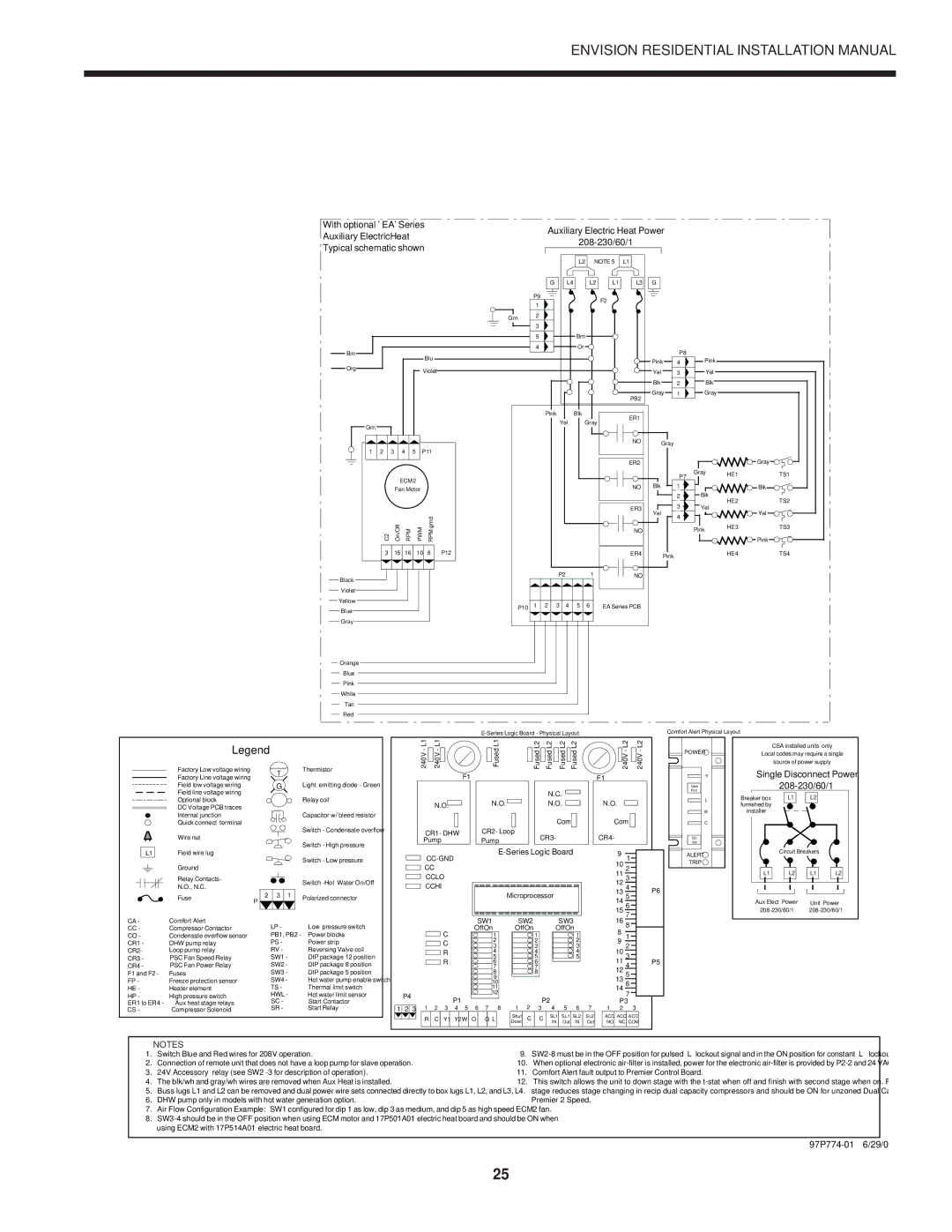
| With optional ' EA' Series |
|
|
|
|
|
|
|
|
| Auxiliary Electric Heat Power |
| |||||||||||
| Auxiliary ElectricHeat |
|
|
|
|
|
|
|
|
|
| ||||||||||||
|
|
|
| ||||||||||||||||||||
| Typical schematic shown |
|
|
| |||||||||||||||||||
|
|
|
|
|
|
|
|
|
|
|
|
|
|
|
|
|
|
| |||||
Brn
Org
Grn
| 1 |
| 2 |
| 3 |
| 4 |
| 5 |
| |||
|
|
|
|
|
| ||||||||
|
|
|
|
|
|
|
|
|
|
|
|
|
|
|
|
|
|
|
|
|
| ECM2 | |||||
|
|
|
|
|
|
| Fan Motor | ||||||
|
|
|
|
|
|
|
|
|
|
|
|
|
|
|
|
|
|
|
|
|
|
|
|
|
|
|
|
|
|
|
| C2 |
| On/Off |
| RPM |
|
| PWM | ||
|
|
|
|
|
|
|
|
|
|
|
|
|
|
|
|
|
| 3 |
| 15 |
| 16 |
| 10 | |||
|
|
|
|
|
|
|
|
|
|
|
|
|
|
|
|
|
|
|
|
|
|
|
|
|
|
|
|
Black
Violet
Yellow
Blue
Gray
|
| L2 | NOTE 5 |
| L1 |
|
|
|
| G | L4 | L2 | L1 | L3 | G |
|
|
| P9 |
| F2 |
|
|
|
|
|
| 1 |
|
|
|
|
|
| |
|
|
|
|
|
|
|
| |
Grn | 2 |
|
|
|
|
|
|
|
|
|
|
|
|
|
|
| |
| 3 |
|
|
|
|
|
|
|
| 5 | Brn |
|
|
|
|
|
|
| 4 | Or |
|
|
|
| P8 |
|
Blu |
|
|
|
|
|
|
| |
|
|
|
|
| Pink | 4 | Pink | |
|
|
|
|
|
| |||
Violet |
|
|
|
|
| Yel | 3 | Yel |
|
|
|
|
|
| Blk | 2 | Blk |
|
|
|
|
| PB2 | Gray | 1 | Gray |
|
|
|
|
|
|
|
|
Pink |
|
| Blk |
| ER1 |
|
|
|
|
| |
| Yel |
|
| Gray | |
|
|
|
|
|
|
|
|
|
|
|
| NO |
| Gray |
|
|
|
|
|
|
|
|
|
|
|
|
|
|
|
| |
P11 |
|
|
|
|
|
|
|
|
|
|
|
|
|
|
|
|
|
|
|
|
| ER2 |
|
|
|
| Gray |
|
|
|
|
|
|
|
|
|
| P7 | Gray | HE1 | TS1 |
|
|
|
|
|
|
|
|
|
|
| |||
|
|
|
|
|
|
|
|
|
|
|
|
| |
|
|
|
|
|
|
|
| NO | Blk | 1 |
|
| Blk |
|
|
|
|
|
|
|
|
|
| 2 | Blk | HE2 | TS2 |
|
|
|
|
|
|
|
|
|
| 3 |
| ||
|
|
|
|
|
|
|
| ER3 | Yel | Yel |
| Yel | |
|
|
|
|
|
|
|
|
| 4 |
|
| ||
|
|
|
|
|
|
|
|
|
|
|
|
| |
grnd |
|
|
|
|
|
|
| NO |
|
| Pink | HE3 | TS3 |
RPM |
|
|
|
|
|
|
|
|
|
|
| ||
|
|
|
|
|
|
|
|
|
|
|
| Pink | |
8 | P12 |
|
|
|
|
|
| ER4 |
| Pink |
| HE4 | TS4 |
|
|
|
|
|
|
|
|
|
|
|
|
| |
|
|
|
|
| P2 |
| 1 | NO |
|
|
|
|
|
| P10 | 1 | 2 | 3 | 4 | 5 | 6 | EA Series PCB |
|
|
|
|
|
Orange
Blue
Pink
White
Tan
Red
Comfort Alert Physical Layout
| Legend |
|
| |
| Factory Low voltage wiring |
| T |
|
| Factory Line voltage wiring |
|
| |
|
|
|
| |
| Field low voltage wiring |
| G |
|
| Field line voltage wiring |
|
|
|
| Optional block |
|
|
|
| DC Voltage PCB traces |
|
|
|
| Internal junction |
|
|
|
| Quick connect terminal |
|
|
|
| Wire nut |
|
|
|
L1 | Field wire lug |
|
|
|
| Ground |
|
|
|
| Relay Contacts- |
|
|
|
| N.O., N.C. |
|
|
|
| Fuse | 2 | 3 | 1 |
| P |
|
| |
|
|
|
| |
Thermistor
Light emitting diode - Green
Relay coil
Capacitor w/ bleed resistor
Switch - Condensate overflow
Switch - High pressure
Switch - Low pressure
Switch
Polarized connector
240V - L1 |
| 240V - L1 |
|
|
| ||
|
|
F1
N.O. ![]()
CR1- DHW
Pump
CC
CCLO
CCHI
|
|
|
| Fused L1 |
|
|
|
|
|
|
| Fused L2 |
| Fused L2 |
| Fused L2 |
| Fused L2 |
| ||||||
|
|
|
|
|
| ||||||||||||||||||||
|
|
|
|
|
| ||||||||||||||||||||
|
|
|
|
|
|
|
|
|
|
|
|
|
|
|
|
|
|
|
|
|
| ||||
|
|
|
|
|
|
|
|
|
|
|
|
|
|
|
| N.C. |
|
|
| ||||||
|
|
|
|
|
|
|
|
|
|
|
|
|
|
|
|
|
|
|
|
|
|
| |||
|
|
|
| N.O. |
|
|
|
|
|
|
|
|
| N.O. |
|
|
|
| |||||||
|
|
|
|
|
|
|
|
|
|
|
|
|
|
|
|
| Com |
|
| ||||||
|
|
|
|
|
|
|
|
|
|
|
|
|
|
|
|
|
|
| |||||||
|
|
|
|
|
|
|
|
|
|
|
|
|
|
|
|
|
|
|
|
|
|
|
|
|
|
|
| CR2- Loop |
| CR3- |
|
|
|
|
|
|
|
|
| ||||||||||||
|
| Pump |
|
|
|
|
|
|
|
|
|
|
|
|
|
|
|
| |||||||
|
|
|
|
|
|
|
|
|
|
|
|
|
|
|
|
|
|
|
|
| |||||
|
|
|
|
|
|
| |||||||||||||||||||
|
|
|
|
|
|
|
|
|
|
|
|
|
|
|
|
|
|
|
|
|
|
|
|
|
|
|
|
|
|
|
|
| Microprocessor |
|
|
|
|
|
|
|
|
| |||||||||
|
|
|
|
|
|
|
|
|
|
|
|
|
|
|
|
|
|
|
|
|
|
|
|
|
|
|
|
|
|
|
|
|
|
|
|
|
|
|
|
|
|
|
|
|
|
|
|
|
|
|
|
240V - L2 | 240V - L2 |
F1
| N.O. |
|
|
|
|
|
| |
|
| Com |
|
|
|
|
| |
|
|
|
|
|
|
| ||
CR4- |
|
|
|
|
| |||
|
|
|
|
| ||||
|
|
|
|
|
|
|
|
|
9 |
|
|
|
|
|
| ||
|
|
|
|
|
| |||
1 |
|
|
|
| ||||
10 |
|
|
|
|
| |||
| 2 |
|
|
|
| |||
|
|
|
| |||||
11 |
| 3 |
|
|
|
| ||
12 |
|
|
|
|
| |||
| 4 |
|
|
| P6 | |||
13 |
|
|
|
| ||||
5 |
| |||||||
14 |
|
|
|
|
| |||
6 |
|
|
|
| ||||
15 |
|
|
|
|
| |||
| 7 |
|
|
|
| |||
![]() POWER
POWER ![]()
Y
Data
Port
L
R
C
DC
Sol
ALERT ![]()
TRIP
CSA installed units only Local codes may require a single source of power supply
Single Disconnect Power 208-230/60/1
Breaker box | L1 | L2 |
|
furnished by |
|
|
|
installer |
|
|
|
| Circuit Breakers |
| |
L1 | L2 | L1 | L2 |
Aux Elect Power | Unit Power |
CA - | Comfort Alert | LP - | Low pressure switch |
CC - | Compressor Contactor | ||
CO - | Condensate overflow sensor | PB1, PB2 - | Power blocks |
CR1 - | DHW pump relay | PS - | Power strip |
CR2- | Loop pump relay | RV - | Reversing Valve coil |
CR3 - | PSC Fan Speed Relay | SW1 - | DIP package 12 position |
CR4 - | PSC Fan Power Relay | SW2 - | DIP package 8 position |
F1 and F2 - | Fuses | SW3 - | DIP package 5 position |
FP - | Freeze protection sensor | SW4 - | Hot water pump enable switch |
HE - | Heater element | TS - | Thermal limit switch |
HP - | High pressure switch | HWL - | Hot water limit sensor |
ER1 to ER4 - | Aux heat stage relays | SC - | Start Contactor |
CS - | Compressor Solenoid | SR - | Start Relay |
|
|
|
|
|
|
|
|
| SW1 |
| SW2 |
|
| SW3 |
|
| |
|
|
|
|
| C |
|
| Off On | 1 | Off On |
| Off On |
|
| |||
|
|
|
|
|
|
|
|
|
|
| 1 |
|
| 1 |
| ||
|
|
|
|
| C |
|
|
|
| 2 |
|
| 2 |
|
| 2 |
|
|
|
|
|
|
|
|
|
| 3 |
|
| 3 |
|
| 3 |
| |
|
|
|
|
| R |
|
|
|
| 4 |
|
| 4 |
|
| 4 |
|
|
|
|
|
| R |
|
|
|
| 5 |
|
| 5 |
|
| 5 |
|
|
|
|
|
|
|
|
|
| 6 |
|
| 6 |
|
|
|
| |
|
|
|
|
|
|
|
|
|
| 7 |
|
| 7 |
|
|
|
|
|
|
|
|
|
|
|
|
|
| 8 |
|
| 8 |
|
|
|
|
|
|
|
|
|
|
|
|
|
| 9 |
|
|
|
|
|
|
|
|
|
|
|
|
|
|
|
|
| 10 |
|
|
|
|
|
|
|
|
|
|
|
|
|
|
|
|
| 11 |
|
|
|
|
|
|
|
| P4 |
|
|
|
|
|
|
|
| 12 |
|
|
|
|
|
|
|
|
|
|
|
| P1 |
|
|
|
|
|
| P2 |
|
|
|
| |
|
|
|
|
|
|
|
|
|
|
| 2 |
|
|
|
| ||
1 | 2 | 3 | 1 | 2 | 3 | 4 | 5 | 6 | 7 | 8 | 1 | 3 | 4 | 5 | 6 | 7 | |
|
|
| R | C | Y1 | Y2 | W | O | G L | Shut | C | C | SL1 | SL1 | SL2 | SL2 | |
|
|
| Down | IN | Out | IN | Out | ||||||||||
16 |
|
|
|
|
8 |
|
|
| |
8 |
|
|
| |
|
|
|
| |
1 |
|
|
| |
9 |
|
|
| |
2 |
|
|
| |
10 |
|
|
| |
3 |
|
|
| |
|
|
| ||
11 | 4 |
|
| P5 |
12 |
|
|
|
|
5 |
|
|
| |
13 |
|
|
| |
6 |
|
|
| |
14 |
|
|
| |
7 |
|
|
| |
|
|
|
| |
P3 |
| |||
1 2 3
ACC | ACC | ACC |
NO | NC | COM |
|
|
|
NOTES
1. | Switch Blue and Red wires for 208V operation. | 9. | |
2. | Connection of remote unit that does not have a loop pump for slave operation. | 10. | When optional electronic |
3. | 24V Accessory relay (see SW2 | 11. | Comfort Alert fault output to Premier Control Board. |
4. | The blk/wh and gray/wh wires are removed when Aux Heat is installed. | 12. | This switch allows the unit to down stage with the |
5. | Buss lugs L1 and L2 can be removed and dual power wire sets connected directly to box lugs L1, L2, and L3, L4. |
| stage reduces stage changing in recip dual capacity compressors and should be ON for unzoned Dual Cap E Series or |
6. | DHW pump only in models with hot water generation option. |
| Premier 2 Speed. |
7. | Air Flow Configuration Example: SW1 configured for dip 1 as low, dip 3 as medium, and dip 5 as high speed ECM2 fan. |
|
|
8. |
|
| |
| using ECM2 with 17P514A01 electric heat board. |
|
|
|
|
|
|
|
|
|
|
25