ENVISION RESIDENTIAL INSTALLATION MANUAL
Microprocessor Control (cont.)
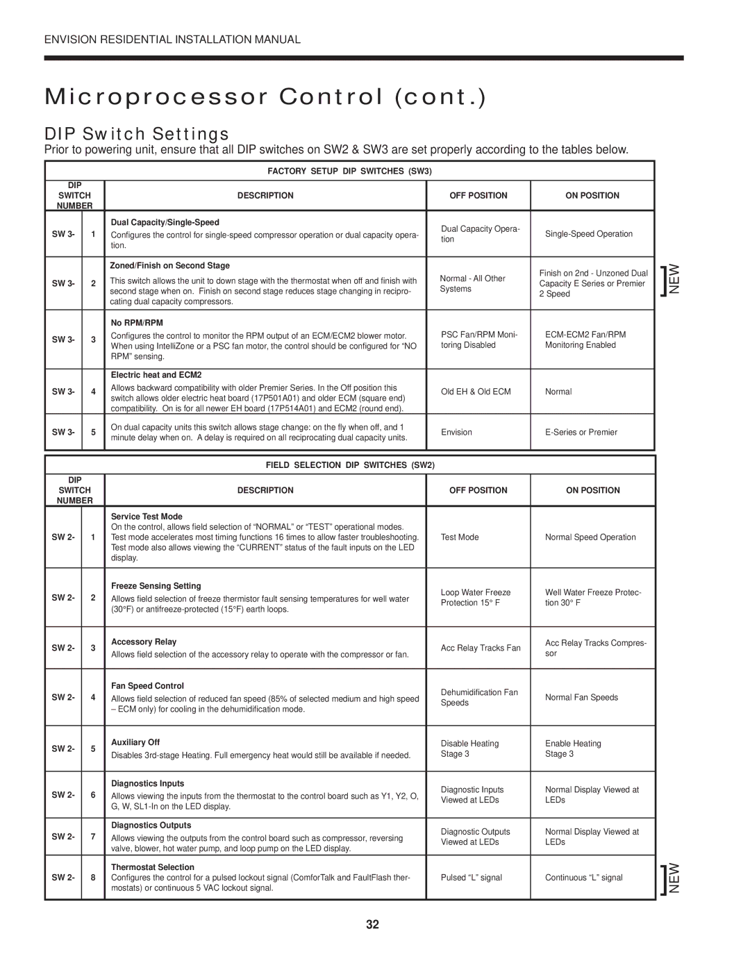
DIP Switch Settings
Prior to powering unit, ensure that all DIP switches on SW2 & SW3 are set properly according to the tables below.
FACTORY SETUP DIP SWITCHES (SW3)
DIP |
|
|
|
|
| |
SWITCH |
| DESCRIPTION |
| OFF POSITION | ON POSITION | |
NUMBER |
|
|
|
| ||
|
|
| Dual |
| Dual Capacity Opera- |
|
SW 3- |
| 1 | Configures the control for |
| ||
|
| tion | ||||
|
|
| tion. |
|
| |
|
|
|
|
|
| |
|
|
|
|
|
|
|
|
|
| Zoned/Finish on Second Stage |
|
| Finish on 2nd - Unzoned Dual |
|
|
| This switch allows the unit to down stage with the thermostat when off and finish with |
| Normal - All Other | |
SW 3- |
| 2 |
| Capacity E Series or Premier | ||
|
| Systems | ||||
| second stage when on. Finish on second stage reduces stage changing in recipro- |
| ||||
|
|
|
| 2 Speed | ||
|
|
|
|
| ||
|
|
| cating dual capacity compressors. |
|
| |
|
|
|
|
|
| |
|
|
|
|
|
|
|
|
|
| No RPM/RPM |
|
|
|
SW 3- |
| 3 | Configures the control to monitor the RPM output of an ECM/ECM2 blower motor. |
| PSC Fan/RPM Moni- | |
| When using IntelliZone or a PSC fan motor, the control should be configured for “NO |
| toring Disabled | Monitoring Enabled | ||
|
|
|
| |||
|
|
| RPM” sensing. |
|
|
|
|
|
|
|
|
|
|
|
|
| Electric heat and ECM2 |
|
|
|
SW 3- |
| 4 | Allows backward compatibility with older Premier Series. In the Off position this |
| Old EH & Old ECM | Normal |
| switch allows older electric heat board (17P501A01) and older ECM (square end) |
| ||||
|
|
|
|
|
| |
|
|
| compatibility. On is for all newer EH board (17P514A01) and ECM2 (round end). |
|
|
|
SW 3- |
| 5 | On dual capacity units this switch allows stage change: on the fly when off, and 1 |
| Envision | |
| minute delay when on. A delay is required on all reciprocating dual capacity units. |
| ||||
|
|
|
|
|
| |
|
|
|
|
|
|
|
|
|
|
|
|
|
|
|
|
| FIELD SELECTION DIP SWITCHES (SW2) |
|
| |
|
|
|
|
|
| |
DIP |
|
|
|
|
| |
SWITCH |
| DESCRIPTION |
| OFF POSITION | ON POSITION | |
NUMBER |
|
|
|
| ||
|
|
| Service Test Mode |
|
|
|
|
|
| On the control, allows field selection of “NORMAL” or “TEST” operational modes. |
|
|
|
SW 2- |
| 1 | Test mode accelerates most timing functions 16 times to allow faster troubleshooting. |
| Test Mode | Normal Speed Operation |
|
|
| Test mode also allows viewing the “CURRENT” status of the fault inputs on the LED |
|
|
|
|
|
| display. |
|
|
|
|
|
|
|
|
|
|
|
|
| Freeze Sensing Setting |
| Loop Water Freeze | Well Water Freeze Protec- |
SW 2- |
| 2 | Allows field selection of freeze thermistor fault sensing temperatures for well water |
| ||
|
| Protection 15° F | tion 30° F | |||
|
|
| (30°F) or |
| ||
|
|
|
|
|
| |
|
|
|
|
|
|
|
SW 2- |
| 3 | Accessory Relay |
| Acc Relay Tracks Fan | Acc Relay Tracks Compres- |
| Allows field selection of the accessory relay to operate with the compressor or fan. |
| sor | |||
|
|
|
|
| ||
|
|
|
|
|
|
|
|
|
| Fan Speed Control |
| Dehumidification Fan |
|
SW 2- |
| 4 | Allows field selection of reduced fan speed (85% of selected medium and high speed |
| Normal Fan Speeds | |
|
| Speeds | ||||
|
|
| – ECM only) for cooling in the dehumidification mode. |
|
| |
|
|
|
|
|
| |
|
|
|
|
|
|
|
SW 2- |
| 5 | Auxiliary Off |
| Disable Heating | Enable Heating |
| Disables |
| Stage 3 | Stage 3 | ||
|
|
|
| |||
|
|
|
|
|
|
|
|
|
| Diagnostics Inputs |
| Diagnostic Inputs | Normal Display Viewed at |
SW 2- |
| 6 | Allows viewing the inputs from the thermostat to the control board such as Y1, Y2, O, |
| ||
|
| Viewed at LEDs | LEDs | |||
|
|
| G, W, |
| ||
|
|
|
|
|
| |
|
|
|
|
|
|
|
|
|
| Diagnostics Outputs |
| Diagnostic Outputs | Normal Display Viewed at |
SW 2- |
| 7 | Allows viewing the outputs from the control board such as compressor, reversing |
| ||
|
| Viewed at LEDs | LEDs | |||
|
|
| valve, blower, hot water pump, and loop pump on the LED display. |
| ||
|
|
|
|
|
| |
|
|
|
|
|
|
|
|
|
| Thermostat Selection |
|
|
|
SW 2- |
| 8 | Configures the control for a pulsed lockout signal (ComforTalk and FaultFlash ther- |
| Pulsed “L” signal | Continuous “L” signal |
|
|
| mostats) or continuous 5 VAC lockout signal. |
|
|
|
|
|
|
|
|
|
|
]NEW
]NEW
32