CONNECTING MOTOR CORD TO SWITCH ASSEMBLY
 Disconnect the machine from the power source!
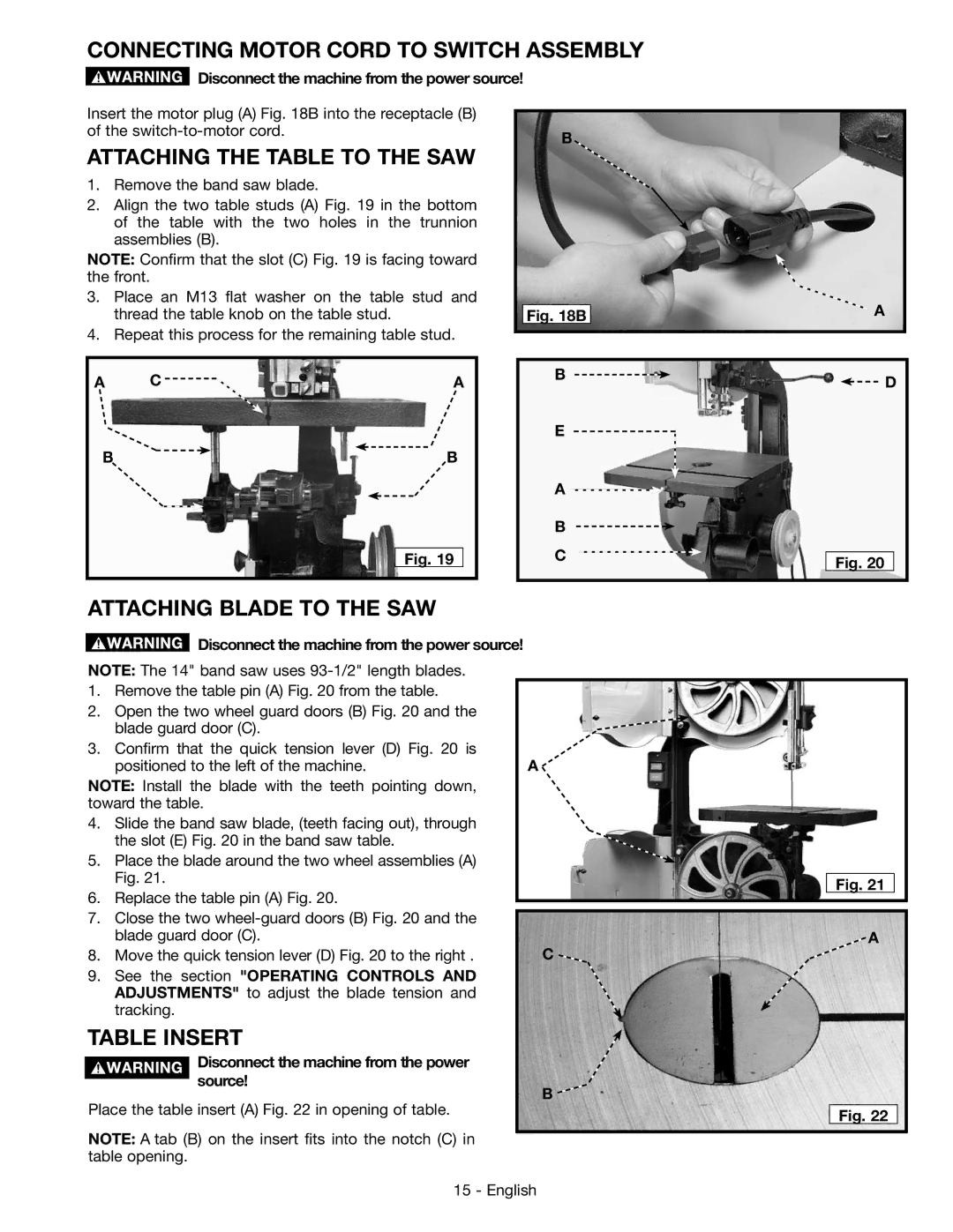
Insert the motor plug (A) Fig. 18B into the receptacle (B) |
|
of the | B |
|
ATTACHING THE TABLE TO THE SAW
1.Remove the band saw blade.
2.Align the two table studs (A) Fig. 19 in the bottom of the table with the two holes in the trunnion assemblies (B).
NOTE: Confirm that the slot (C) Fig. 19 is facing toward the front.
3. | Place an M13 flat washer on the table stud and |
|
| thread the table knob on the table stud. | Fig. 18B |
4. | Repeat this process for the remaining table stud. |
|
![]() A
A
A C ![]()
![]() A
A
B ![]() B
B
Fig. 19
B![]()
E
A ![]()
B
C
![]() D
D
Fig. 20
ATTACHING BLADE TO THE SAW
![]() Disconnect the machine from the power source!
Disconnect the machine from the power source!
NOTE: The 14" band saw uses
1. | Remove the table pin (A) Fig. 20 from the table. |
|
2. | Open the two wheel guard doors (B) Fig. 20 and the |
|
| blade guard door (C). |
|
3. | Confirm that the quick tension lever (D) Fig. 20 is | A |
| positioned to the left of the machine. |
NOTE: Install the blade with the teeth pointing down, toward the table.
4.Slide the band saw blade, (teeth facing out), through the slot (E) Fig. 20 in the band saw table.
5.Place the blade around the two wheel assemblies (A) Fig. 21.
6.Replace the table pin (A) Fig. 20.
7.Close the two
8. Move the quick tension lever (D) Fig. 20 to the right . | C |
9.See the section "OPERATING CONTROLS AND ADJUSTMENTS" to adjust the blade tension and tracking.
Fig. 21
A
TABLE INSERT
Disconnect the machine from the power source!
Place the table insert (A) Fig. 22 in opening of table.
B ![]()
Fig. 22
NOTE: A tab (B) on the insert fits into the notch (C) in table opening.
15 - English