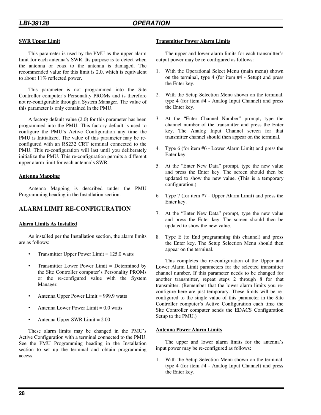
LBI-39128 specifications
Ericsson LBI-39128 is a comprehensive communication solution designed to meet the ever-evolving demands of modern telecommunications. It is renowned for its ability to enhance network performance while providing a robust framework for various communication technologies. This product primarily targets service providers, enabling them to maximize their operational efficiency and improve service delivery.One of the key features of the LBI-39128 is its versatility in supporting multiple generation technologies, including 2G, 3G, LTE, and even 5G. This ensures that service providers can seamlessly integrate their existing infrastructure and gradually evolve towards more advanced network capabilities without the need for a complete overhaul. The product caters to a wide array of deployment scenarios, from urban environments with high user density to rural areas requiring expansive coverage.
In terms of network performance, the LBI-39128 excels with its advanced radio technologies. It employs Massive MIMO (Multiple Input Multiple Output) and beamforming techniques, which significantly enhance spectral efficiency and improve user experience. With multiple antennas transmitting and receiving signals simultaneously, users benefit from increased throughput and reduced latency, essential for applications such as video streaming and real-time communications.
Another critical characteristic of the Ericsson LBI-39128 is its focus on energy efficiency. The product integrates intelligent power management systems that optimize energy consumption, thereby reducing operational costs for service providers. This aligns with the growing emphasis on sustainable practices within the telecommunications industry.
Moreover, the LBI-39128 features advanced management and automation capabilities. Its network function virtualization (NFV) support enables operators to deploy virtualized network functions efficiently, allowing for dynamic scaling and resource allocation based on real-time demand. This agility is crucial for handling varying loads and enhancing the overall resilience of the network.
Security is also a primary consideration in the design of the LBI-39128. It incorporates robust encryption methods and secure access protocols to protect sensitive data and ensure the integrity of communication channels. This is particularly important in an age where cyber threats are becoming increasingly prevalent.
In summary, the Ericsson LBI-39128 is a state-of-the-art telecommunications solution that stands out due to its support for multiple technologies, advanced radio capabilities, energy efficiency, automated management, and robust security features. Its design reflects the needs of contemporary service providers, allowing them to build and sustain high-performance networks that meet the demands of future communications.

