d)Loosen but do not remove the two (2) axle pivot bolts and the two (2) axle adjustment bolts (See Figure 11).
e)Place a jack under the rear center of the engine deck.
f)Raise the back end of the engine deck up enough to remove the two (2) axle adjustment bolts.
g)With the jack, raise or lower the back end of the engine deck so that two (2) axle adjustment bolts can be reinstalled in desired hole location. A tapered punch can be used to help align the holes.
h)Retighten all four (4) bolts, lower unit and remove jack.
i)Install mower deck belt shield.
j)Adjust wheel drive and brake linkages as required. (See Section 4.1.5).
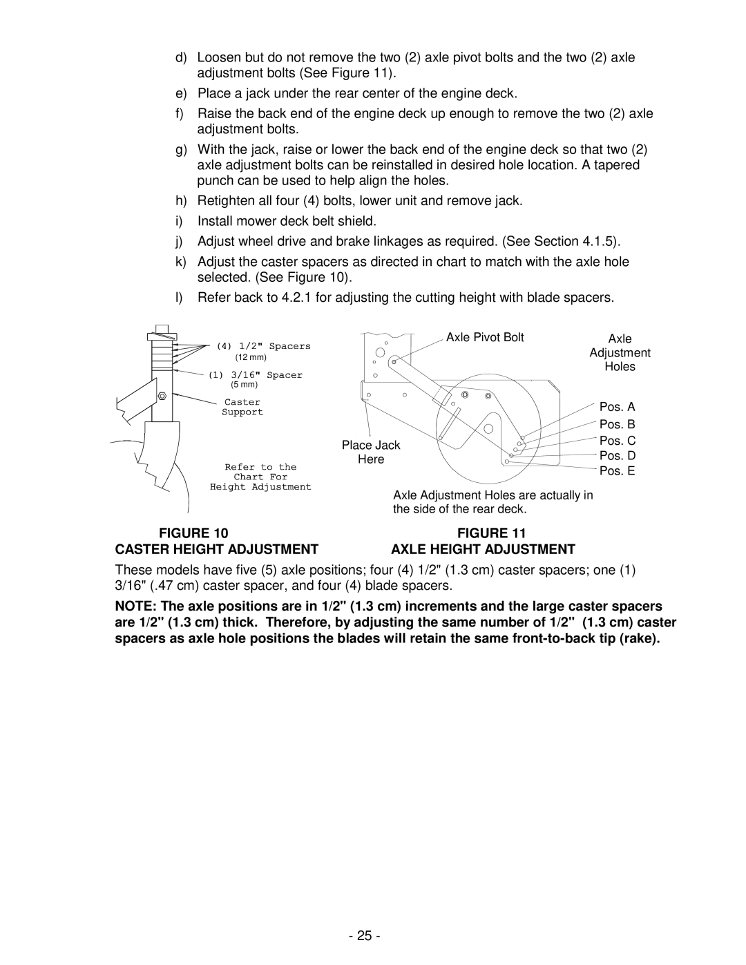
k)Adjust the caster spacers as directed in chart to match with the axle hole selected. (See Figure 10).
l)Refer back to 4.2.1 for adjusting the cutting height with blade spacers.
(12 mm)
(5 mm)
Axle Pivot Bolt | Axle | |
| Adjustment | |
| Holes | |
| Pos. A | |
| Pos. B | |
Place Jack | Pos. C | |
Pos. D | ||
Here | ||
| Pos. E |
Axle Adjustment Holes are actually in the side of the rear deck.
FIGURE 10 | FIGURE 11 |
CASTER HEIGHT ADJUSTMENT | AXLE HEIGHT ADJUSTMENT |
These models have five (5) axle positions; four (4) 1/2" (1.3 cm) caster spacers; one (1) 3/16" (.47 cm) caster spacer, and four (4) blade spacers.
NOTE: The axle positions are in 1/2" (1.3 cm) increments and the large caster spacers are 1/2" (1.3 cm) thick. Therefore, by adjusting the same number of 1/2" (1.3 cm) caster spacers as axle hole positions the blades will retain the same
- 25 -