Again, run the engine at
If the mower engine does not stop under any of the above mentioned conditions, DO NOT OPERATE. Contact your authorized Exmark service dealer.
IMPORTANT: It is essential that all Operator Safety Mechanisms, be in place and in proper operating condition prior to mowing.
4.1.5Check Brake and Wheel Drive Linkage Adjustment.
Service Interval: Daily
a)Check for correct brake adjustment:
Place the drive levers in the “park brake” position. The mower should not move forward or backward. If it does, tighten the wingnuts.
Place the drive levers in the “neutral lock” position. The mower should move forward and backward freely. If it does not, brake adjustment is necessary.
b)Adjust brakes by adjusting wingnut on the upper end of each brake rod. Tighten the wingnut until the brakes engage when the drive levers are squeezed enough to allow the neutral lock/park brake latches to be placed into the “park brake” position.
See Figure 3 for Standard Pistol Grip handles and Figure 4 for ECS handles.
NOTE: The neutral lock/park brake latches must be able to be moved into the park brake position, if not, the brake linkages must be adjusted again.
c)Check for correct wheel drive linkage adjustment:
For Pistol Grip Handles:
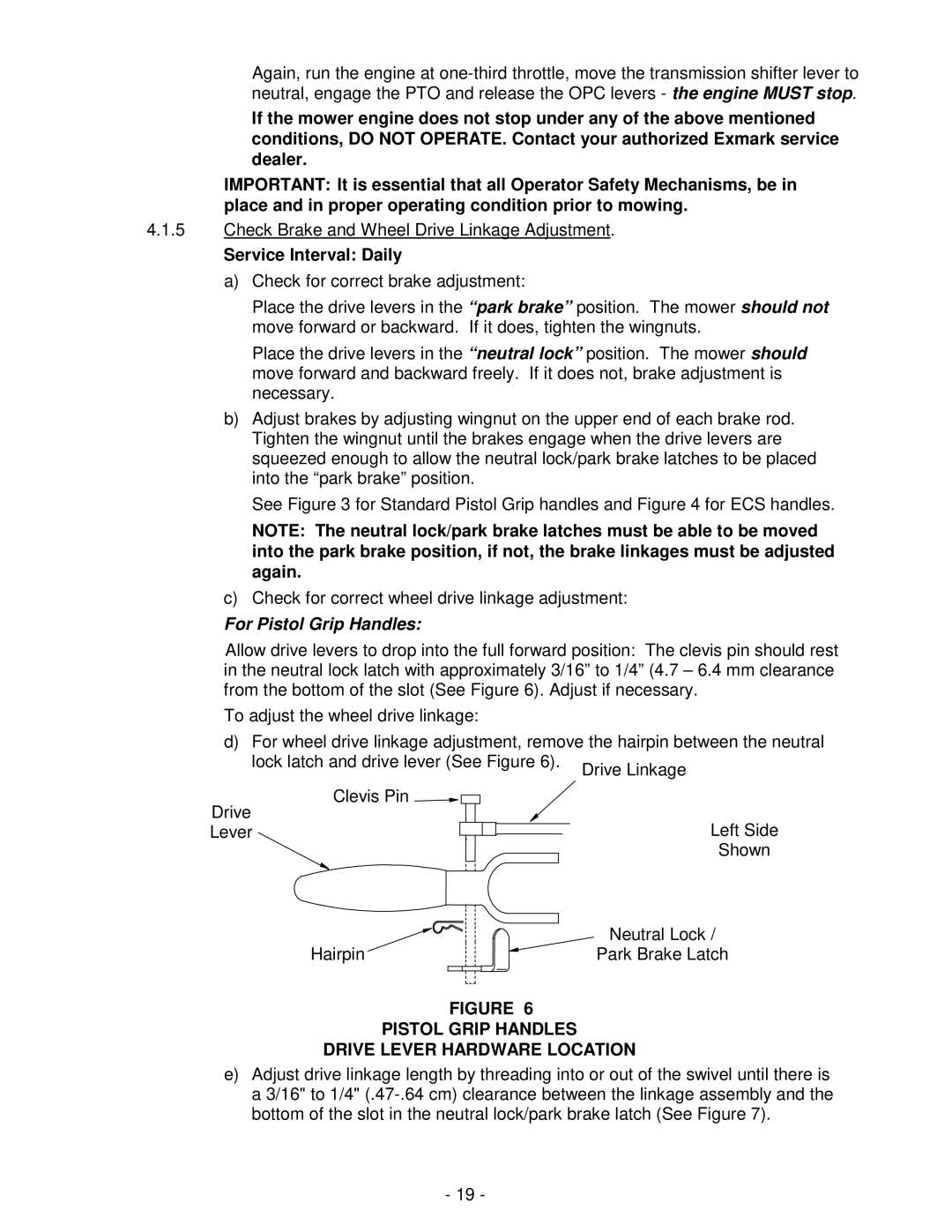
Allow drive levers to drop into the full forward position: The clevis pin should rest in the neutral lock latch with approximately 3/16” to 1/4” (4.7 – 6.4 mm clearance from the bottom of the slot (See Figure 6). Adjust if necessary.
To adjust the wheel drive linkage:
d) For wheel drive linkage adjustment, remove the hairpin between the neutral lock latch and drive lever (See Figure 6).
Clevis Pin ![]()
Drive
LeverLeft Side
Shown
Hairpin | Neutral Lock / |
Park Brake Latch |
FIGURE 6
PISTOL GRIP HANDLES
DRIVE LEVER HARDWARE LOCATION
e)Adjust drive linkage length by threading into or out of the swivel until there is a 3/16" to 1/4"
-19 -