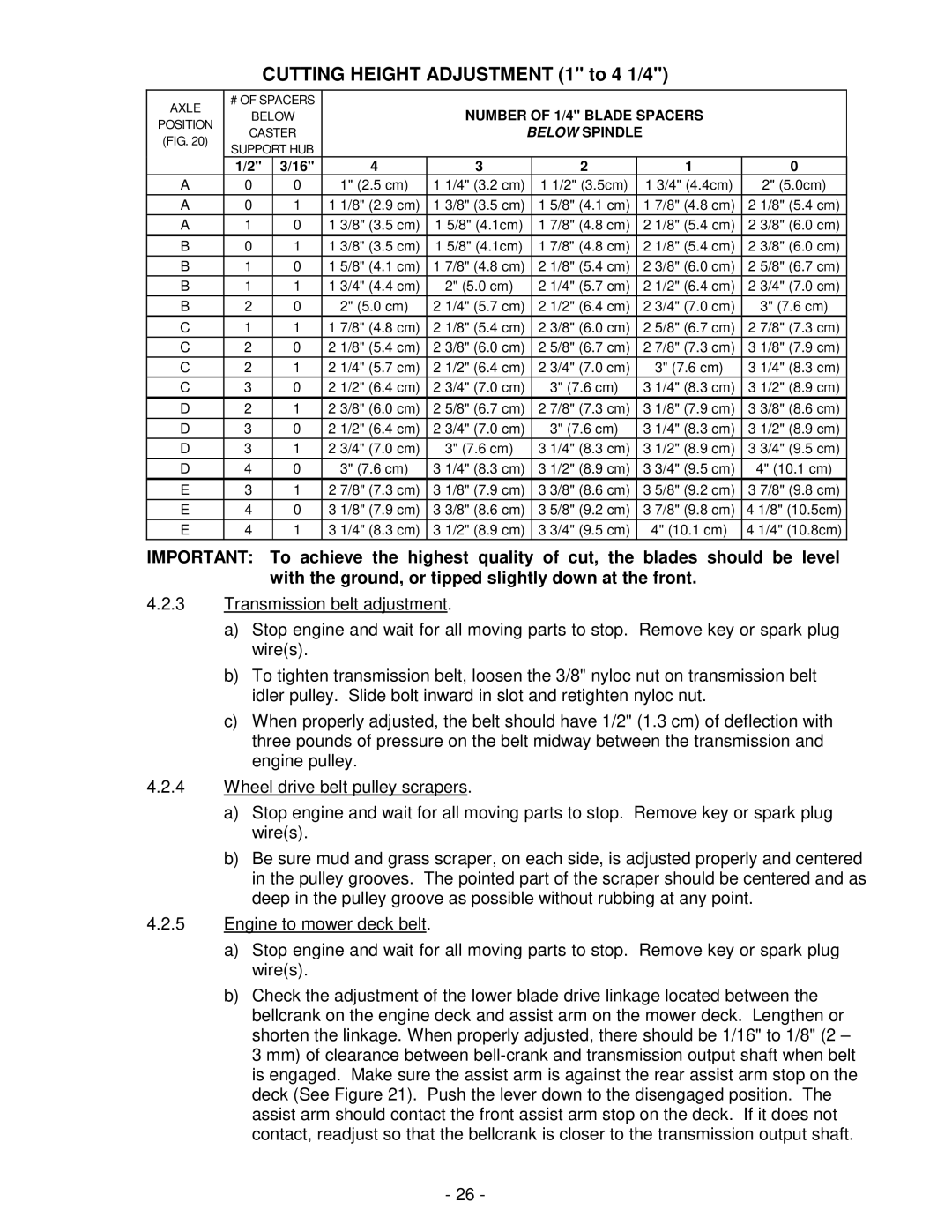
CUTTING HEIGHT ADJUSTMENT (1" to 4 1/4")
AXLE | # OF SPACERS |
|
|
|
|
|
|
|
|
|
|
|
| |
BELOW |
|
|
| NUMBER OF 1/4" BLADE SPACERS |
|
| ||||||||
POSITION |
|
|
|
|
| |||||||||
CASTER |
|
|
|
| BELOW SPINDLE |
|
|
|
| |||||
(FIG. 20) |
|
|
|
|
|
|
|
| ||||||
SUPPORT HUB |
|
|
|
|
|
|
|
|
|
|
|
| ||
|
|
|
|
|
|
|
|
|
|
|
|
| ||
| 1/2" | 3/16" |
| 4 |
| 3 |
|
| 2 |
|
| 1 |
| 0 |
A | 0 | 0 |
| 1" (2.5 cm) | 1 | 1/4" (3.2 cm) |
| 1 1/2" (3.5cm) |
| 1 3/4" (4.4cm) |
| 2" (5.0cm) | ||
A | 0 | 1 | 1 | 1/8" (2.9 cm) | 1 | 3/8" (3.5 cm) |
| 1 | 5/8" (4.1 cm) |
| 1 | 7/8" (4.8 cm) | 2 | 1/8" (5.4 cm) |
A | 1 | 0 | 1 | 3/8" (3.5 cm) | 1 5/8" (4.1cm) |
| 1 | 7/8" (4.8 cm) |
| 2 | 1/8" (5.4 cm) | 2 | 3/8" (6.0 cm) | |
B | 0 | 1 | 1 | 3/8" (3.5 cm) | 1 5/8" (4.1cm) |
| 1 | 7/8" (4.8 cm) |
| 2 | 1/8" (5.4 cm) | 2 | 3/8" (6.0 cm) | |
B | 1 | 0 | 1 | 5/8" (4.1 cm) | 1 | 7/8" (4.8 cm) |
| 2 | 1/8" (5.4 cm) |
| 2 | 3/8" (6.0 cm) | 2 | 5/8" (6.7 cm) |
B | 1 | 1 | 1 | 3/4" (4.4 cm) |
| 2" (5.0 cm) |
| 2 | 1/4" (5.7 cm) |
| 2 | 1/2" (6.4 cm) | 2 | 3/4" (7.0 cm) |
B | 2 | 0 |
| 2" (5.0 cm) | 2 | 1/4" (5.7 cm) |
| 2 | 1/2" (6.4 cm) |
| 2 | 3/4" (7.0 cm) |
| 3" (7.6 cm) |
C | 1 | 1 | 1 | 7/8" (4.8 cm) | 2 | 1/8" (5.4 cm) |
| 2 | 3/8" (6.0 cm) |
| 2 | 5/8" (6.7 cm) | 2 | 7/8" (7.3 cm) |
C | 2 | 0 | 2 | 1/8" (5.4 cm) | 2 | 3/8" (6.0 cm) |
| 2 | 5/8" (6.7 cm) |
| 2 | 7/8" (7.3 cm) | 3 | 1/8" (7.9 cm) |
C | 2 | 1 | 2 | 1/4" (5.7 cm) | 2 | 1/2" (6.4 cm) |
| 2 | 3/4" (7.0 cm) |
|
| 3" (7.6 cm) | 3 | 1/4" (8.3 cm) |
C | 3 | 0 | 2 | 1/2" (6.4 cm) | 2 | 3/4" (7.0 cm) |
|
| 3" (7.6 cm) |
| 3 | 1/4" (8.3 cm) | 3 | 1/2" (8.9 cm) |
D | 2 | 1 | 2 | 3/8" (6.0 cm) | 2 | 5/8" (6.7 cm) |
| 2 | 7/8" (7.3 cm) |
| 3 | 1/8" (7.9 cm) | 3 | 3/8" (8.6 cm) |
D | 3 | 0 | 2 | 1/2" (6.4 cm) | 2 | 3/4" (7.0 cm) |
|
| 3" (7.6 cm) |
| 3 | 1/4" (8.3 cm) | 3 | 1/2" (8.9 cm) |
D | 3 | 1 | 2 | 3/4" (7.0 cm) |
| 3" (7.6 cm) |
| 3 | 1/4" (8.3 cm) |
| 3 | 1/2" (8.9 cm) | 3 | 3/4" (9.5 cm) |
D | 4 | 0 |
| 3" (7.6 cm) | 3 | 1/4" (8.3 cm) |
| 3 | 1/2" (8.9 cm) |
| 3 | 3/4" (9.5 cm) |
| 4" (10.1 cm) |
E | 3 | 1 | 2 | 7/8" (7.3 cm) | 3 | 1/8" (7.9 cm) |
| 3 | 3/8" (8.6 cm) |
| 3 | 5/8" (9.2 cm) | 3 | 7/8" (9.8 cm) |
E | 4 | 0 | 3 | 1/8" (7.9 cm) | 3 | 3/8" (8.6 cm) |
| 3 | 5/8" (9.2 cm) |
| 3 | 7/8" (9.8 cm) | 4 1/8" (10.5cm) | |
E | 4 | 1 | 3 | 1/4" (8.3 cm) | 3 | 1/2" (8.9 cm) |
| 3 | 3/4" (9.5 cm) |
|
| 4" (10.1 cm) | 4 1/4" (10.8cm) | |
IMPORTANT: To achieve the highest quality of cut, the blades should be level with the ground, or tipped slightly down at the front.
4.2.3Transmission belt adjustment.
a)Stop engine and wait for all moving parts to stop. Remove key or spark plug wire(s).
b)To tighten transmission belt, loosen the 3/8" nyloc nut on transmission belt idler pulley. Slide bolt inward in slot and retighten nyloc nut.
c)When properly adjusted, the belt should have 1/2" (1.3 cm) of deflection with three pounds of pressure on the belt midway between the transmission and engine pulley.
4.2.4Wheel drive belt pulley scrapers.
a)Stop engine and wait for all moving parts to stop. Remove key or spark plug wire(s).
b)Be sure mud and grass scraper, on each side, is adjusted properly and centered in the pulley grooves. The pointed part of the scraper should be centered and as deep in the pulley groove as possible without rubbing at any point.
4.2.5Engine to mower deck belt.
a)Stop engine and wait for all moving parts to stop. Remove key or spark plug wire(s).
b)Check the adjustment of the lower blade drive linkage located between the bellcrank on the engine deck and assist arm on the mower deck. Lengthen or shorten the linkage. When properly adjusted, there should be 1/16" to 1/8" (2 – 3 mm) of clearance between
-26 -