TOC
TOC
|
| INSTALLATION |
| INPUT CONNECTIONS | GROUND CONNECTION |
|
| The frame of the |
Return to Section
Return to Master
WARNING
ELECTRIC SHOCK can kill.
• Have a qualified electrician install and service this equipment.
•Turn the input power off at the fuse box before working on this equipment.
•Do not touch electrically hot parts.
ed. A ground terminal marked with the symbol ![]() is mounted on the case bottom directly behind the input power switch for this purpose. The ground lead of the input power cord that is attached to the machine must be connected to this ground terminal. See the National Electric Code for details on proper grounding methods. Install in accordance with all local and national electrical codes.
is mounted on the case bottom directly behind the input power switch for this purpose. The ground lead of the input power cord that is attached to the machine must be connected to this ground terminal. See the National Electric Code for details on proper grounding methods. Install in accordance with all local and national electrical codes.
Return to Section TOC
Return to Master TOC
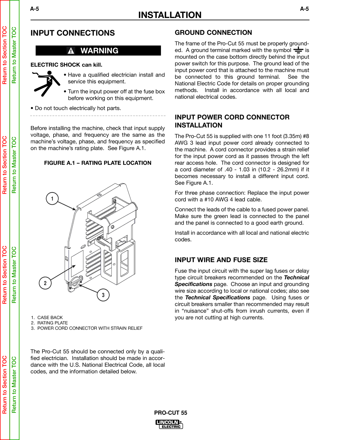
Before installing the machine, check that input supply voltage, phase, and frequency are the same as the machine’s voltage, phase, and frequency as specified on the machine’s rating plate. See Figure A.1.
FIGURE A.1 – RATING PLATE LOCATION
1
INPUT POWER CORD CONNECTOR INSTALLATION
The
For three phase connection: Replace the input power cord with a #10 AWG 4 lead cable.
Connect the leads of the cable to a fused power panel. Make sure the green lead is connected to the panel and the panel is connected to a good earth ground.
Install in accordance with all local and national electric codes.
Return to Section TOC
Return to Section TOC
Return to Master TOC
Return to Master TOC
2
3
1.CASE BACK
2.RATING PLATE
3.POWER CORD CONNECTOR WITH STRAIN RELIEF
The
INPUT WIRE AND FUSE SIZE
Fuse the input circuit with the super lag fuses or delay type circuit breakers recommended on the Technical Specifications page. Choose an input and grounding wire size according to local or national codes; also see the Technical Specifications page. Using fuses or circuit breakers smaller than recommended may result in “nuisance”