| TROUBLESHOOTING & REPAIR | |
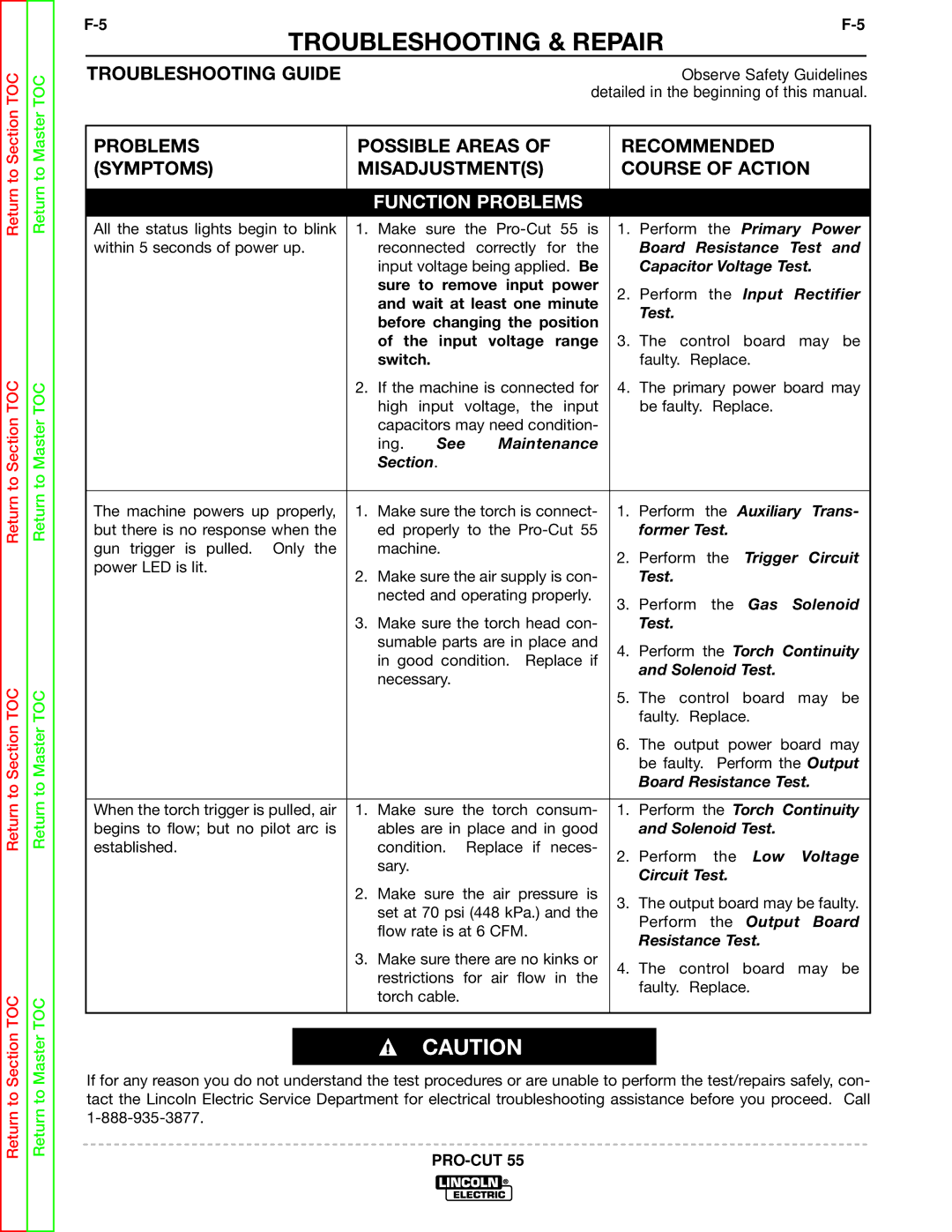
| TROUBLESHOOTING GUIDE | Observe Safety Guidelines |
|
| detailed in the beginning of this manual. |
PROBLEMS | POSSIBLE AREAS OF | RECOMMENDED |
| ||||||||
(SYMPTOMS) | MISADJUSTMENT(S) | COURSE OF ACTION | |||||||||
|
|
|
|
|
|
|
| ||||
|
| FUNCTION PROBLEMS |
|
|
|
|
| ||||
All the status lights begin to blink | 1. Make | sure | the | 1. | Perform | the | Primary Power | ||||
within 5 seconds of power up. |
| reconnected correctly for the |
| Board Resistance | Test and | ||||||
|
| input voltage being applied. Be |
| Capacitor Voltage Test. | |||||||
|
| sure to remove input power | 2. Perform the Input Rectifier | ||||||||
|
| and wait at least one minute | |||||||||
|
|
| Test. |
|
|
| |||||
|
| before changing the position |
|
|
|
| |||||
|
|
|
|
|
|
| |||||
|
| of the input voltage range | 3. | The control board may be | |||||||
|
| switch. |
|
|
|
| faulty. Replace. |
| |||
| 2. | If the machine is connected for | 4. | The primary power board may | |||||||
|
| high input voltage, the input |
| be faulty. Replace. |
| ||||||
|
| capacitors may need condition- |
|
|
|
|
| ||||
|
| ing. | See | Maintenance |
|
|
|
|
| ||
|
| Section. |
|
|
|
|
|
|
|
| |
|
|
|
| ||||||||
The machine powers up properly, | 1. Make sure the torch is connect- | 1. | Perform the Auxiliary Trans- | ||||||||
but there is no response when the |
| ed properly to the |
| former Test. |
|
| |||||
gun trigger is pulled. Only the |
| machine. |
|
|
| 2. | Perform | the | Trigger Circuit | ||
power LED is lit. |
|
|
|
|
|
| |||||
2. Make sure the air supply is con- |
| Test. |
|
|
| ||||||
|
|
|
|
| |||||||
|
| nected and operating properly. | 3. | Perform | the | Gas | Solenoid | ||||
|
|
|
|
|
|
| |||||
| 3. | Make sure the torch head con- |
| Test. |
|
|
| ||||
|
| sumable parts are in place and | 4. | Perform the Torch Continuity | |||||||
|
| in good condition. | Replace if | ||||||||
|
|
| and Solenoid Test. |
| |||||||
|
| necessary. |
|
|
|
|
| ||||
|
|
|
|
|
|
|
|
|
| ||
|
|
|
|
|
|
| 5. | The control | board | may be | |
|
|
|
|
|
|
|
| faulty. Replace. |
| ||
|
|
|
|
|
|
| 6. | The output power board may | |||
|
|
|
|
|
|
|
| be faulty. Perform the Output | |||
|
|
|
|
|
|
|
| Board Resistance Test. | |||
|
|
|
|
|
|
| |||||
When the torch trigger is pulled, air | 1. Make | sure | the | torch consum- | 1. | Perform the Torch Continuity | |||||
begins to flow; but no pilot arc is |
| ables are in place and in good |
| and Solenoid Test. |
| ||||||
established. |
| condition. | Replace if neces- | 2. | Perform | the | Low | Voltage | |||
|
| sary. |
|
|
|
| |||||
|
|
|
|
|
|
| Circuit Test. |
|
| ||
|
|
|
|
|
|
|
|
|
| ||
| 2. | Make | sure | the | air | pressure is | 3. The output board may be faulty. | ||||
|
| set at 70 psi (448 kPa.) and the | |||||||||
|
|
| Perform | the | Output Board | ||||||
|
| flow rate is at 6 CFM. |
| ||||||||
|
|
| Resistance Test. |
| |||||||
|
|
|
|
|
|
|
|
| |||
| 3. Make sure there are no kinks or | 4. | The control board may be | ||||||||
|
| restrictions | for | air | flow in the | ||||||
|
|
| faulty. Replace. |
| |||||||
|
| torch cable. |
|
|
|
|
| ||||
|
|
|
|
|
|
|
|
|
| ||
|
|
|
|
|
|
|
|
|
|
|
|
CAUTION
If for any reason you do not understand the test procedures or are unable to perform the test/repairs safely, con- tact the Lincoln Electric Service Department for electrical troubleshooting assistance before you proceed. Call