Return to Section TOC
Return to Section TOC
Return to Master TOC
Return to Master TOC
|
| THEORY OF OPERATION |
|
| ||||||
|
|
|
|
|
| |||||
|
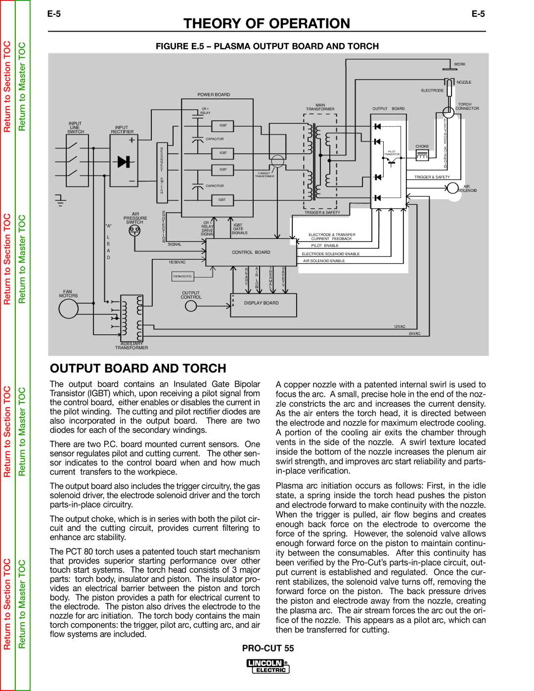
| FIGURE E.5 – PLASMA OUTPUT BOARD AND TORCH |
|
| ||||||
|
|
|
|
|
|
|
|
|
| WORK |
|
|
|
|
|
|
|
|
|
| NOZZLE |
|
|
| POWER BOARD |
|
|
|
|
| ELECTRODE |
|
|
|
|
|
|
|
|
|
|
| |
|
|
|
|
|
|
| MAIN |
|
| TORCH |
|
|
| CR 1 |
|
|
| TRANSFORMER | OUTPUT BOARD |
| CONNECTOR |
|
|
| RELAY |
|
|
|
|
|
|
|
|
|
|
|
|
|
|
|
|
| E |
INPUT |
|
| IGBT |
|
|
|
|
|
| L |
LINE | INPUT |
|
|
|
|
|
|
| E | |
|
|
|
|
|
|
|
| C | ||
SWITCH | RECTIFIER |
|
|
|
|
|
|
|
| T |
|
|
|
|
|
|
|
|
|
| R |
|
|
| CAPACITOR |
|
|
|
|
|
| O |
|
|
|
|
|
|
|
|
| D | |
|
|
|
|
|
|
|
|
| CHOKE | E |
|
| R |
|
|
|
|
|
| S | |
|
|
|
|
|
|
|
|
| ||
|
| E | IGBT |
|
|
|
| PILOT |
| O |
|
| C |
|
|
|
| TRANSISTOR |
| L | |
|
|
|
|
|
|
|
| E | ||
|
| O |
|
|
|
|
|
|
| |
|
| N |
|
|
|
|
|
|
| N |
|
|
|
|
|
|
|
|
| O | |
|
| N |
|
|
|
|
|
|
| |
|
|
|
|
|
|
|
|
| I | |
|
| E |
|
|
|
|
|
|
| |
|
|
|
|
|
|
|
|
| D | |
|
| C | IGBT |
|
|
|
|
|
| |
|
| T |
|
|
|
|
|
|
| |
|
|
|
| CURRENT |
|
|
|
| ||
|
|
|
|
|
|
|
|
| ||
|
| S |
|
| TRANSFORMER |
|
| TRIGGER & SAFETY | ||
|
|
|
|
|
|
|
| |||
|
| W |
|
|
|
|
|
|
|
|
|
| I | CAPACITOR |
|
|
|
|
|
| AIR |
|
| T |
|
|
|
|
|
| ||
|
| C |
|
|
|
|
|
|
| SOLENOID |
|
| H |
|
|
|
|
|
|
|
|
|
|
| IGBT |
|
|
|
|
|
|
|
| AIR | P |
|
|
|
| TRIGGER & SAFETY |
|
|
|
| R |
|
|
|
|
|
|
|
| |
| PRESSURE | O |
|
|
|
|
|
|
|
|
| SWITCH | T | CR 1 | IGBT |
|
|
|
|
|
|
| "A" | E | RELAY |
|
|
|
|
|
| |
|
| C | DRIVE | GATE |
|
|
|
|
|
|
|
| T | SIGNALS |
|
|
|
|
|
| |
|
| SIGNAL |
|
| ELECTRODE & TRANSFER |
|
|
| ||
| L | I |
|
|
|
|
|
| ||
| O |
|
|
|
| CURRENT FEEDBACK |
|
|
| |
| E | N | SIGNAL |
|
|
|
|
|
|
|
|
|
|
|
| PILOT ENABLE |
|
|
| ||
|
|
|
|
|
|
|
|
|
| |
| A |
|
| CONTROL BOARD | ELECTRODE SOLENOID ENABLE |
|
|
| ||
|
|
|
|
|
|
| ||||
| D |
|
|
|
|
|
|
|
| |
|
|
|
|
|
| AIR SOLENOID ENABLE |
|
|
| |
|
|
| 18/36VAC |
|
|
|
|
|
| |
|
|
|
|
|
|
|
|
|
| |
|
|
|
| R | A | T | S |
|
|
|
|
|
|
| E | I | H | A |
|
|
|
|
|
| THERMOSTATS | R | E | F |
|
|
| |
|
|
| A |
|
|
| ||||
|
|
|
| L | R | E |
|
|
| |
|
|
|
| D | M | T |
|
|
| |
|
|
|
| Y | O | A | Y |
|
|
|
FAN |
|
|
|
| W | L |
|
|
|
|
|
| OUTPUT |
|
|
|
|
|
|
| |
MOTORS |
|
|
|
|
|
|
|
|
| |
|
| CONTROL |
|
|
|
|
|
|
| |
|
|
|
|
|
|
|
|
|
| |
|
|
|
| DISPLAY BOARD |
|
|
|
| ||
|
|
|
|
|
|
|
| 12VAC |
|
|
|
|
|
|
|
|
|
|
| 24VAC |
|
AUXILIARY
TRANSFORMER
Return to Section TOC
Return to Section TOC
Return to Master TOC
Return to Master TOC
OUTPUT BOARD AND TORCH
The output board contains an Insulated Gate Bipolar Transistor (IGBT) which, upon receiving a pilot signal from the control board, either enables or disables the current in the pilot winding. The cutting and pilot rectifier diodes are also incorporated in the output board. There are two diodes for each of the secondary windings.
There are two P.C. board mounted current sensors. One sensor regulates pilot and cutting current. The other sen- sor indicates to the control board when and how much current transfers to the workpiece.
The output board also includes the trigger circuitry, the gas solenoid driver, the electrode solenoid driver and the torch
The output choke, which is in series with both the pilot cir- cuit and the cutting circuit, provides current filtering to enhance arc stability.
The PCT 80 torch uses a patented touch start mechanism that provides superior starting performance over other touch start systems. The torch head consists of 3 major parts: torch body, insulator and piston. The insulator pro- vides an electrical barrier between the piston and torch body. The piston provides a path for electrical current to the electrode. The piston also drives the electrode to the nozzle for arc initiation. The torch body contains the main torch components: the trigger, pilot arc, cutting arc, and air flow systems are included.
A copper nozzle with a patented internal swirl is used to focus the arc. A small, precise hole in the end of the noz- zle constricts the arc and increases the current density. As the air enters the torch head, it is directed between the electrode and nozzle for maximum electrode cooling. A portion of the cooling air exits the chamber through vents in the side of the nozzle. A swirl texture located inside the bottom of the nozzle increases the plenum air swirl strength, and improves arc start reliability and parts-
Plasma arc initiation occurs as follows: First, in the idle state, a spring inside the torch head pushes the piston and electrode forward to make continuity with the nozzle. When the trigger is pulled, air flow begins and creates enough back force on the electrode to overcome the force of the spring. However, the solenoid valve allows enough forward force on the piston to maintain continu- ity between the consumables. After this continuity has been verified by the