Return to Section TOC
Return to Master TOC
TROUBLESHOOTING & REPAIR
OUTPUT POWER BOARD REMOVAL & REPLACEMENT (continued)
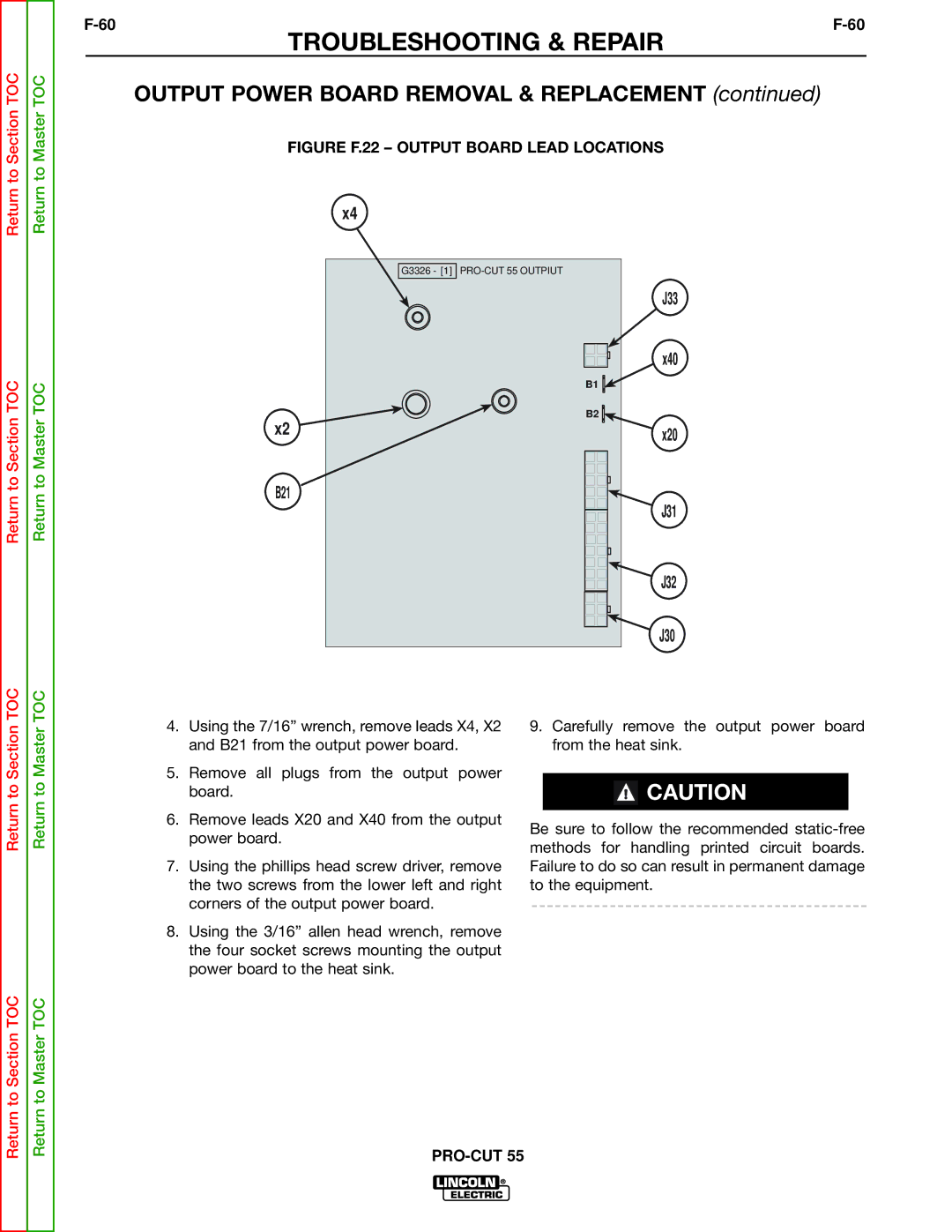
FIGURE F.22 – OUTPUT BOARD LEAD LOCATIONS
x4
Return to Section TOC
Return to Master TOC
x2
B21
G3326 - [1]
B1 ![]()
B2 ![]()
J33
x40
x20
J31
J32
J30
Return to Section TOC
Return to Master TOC
4.Using the 7/16” wrench, remove leads X4, X2 and B21 from the output power board.
5.Remove all plugs from the output power board.
6.Remove leads X20 and X40 from the output power board.
7.Using the phillips head screw driver, remove the two screws from the lower left and right corners of the output power board.
8.Using the 3/16” allen head wrench, remove the four socket screws mounting the output power board to the heat sink.
9.Carefully remove the output power board from the heat sink.
![]() CAUTION
CAUTION
Be sure to follow the recommended
Return to Section TOC
Return to Master TOC