Return to Section TOC
Return to Master TOC
TROUBLESHOOTING & REPAIR
LOW VOLTAGE CIRCUIT TEST (continued)
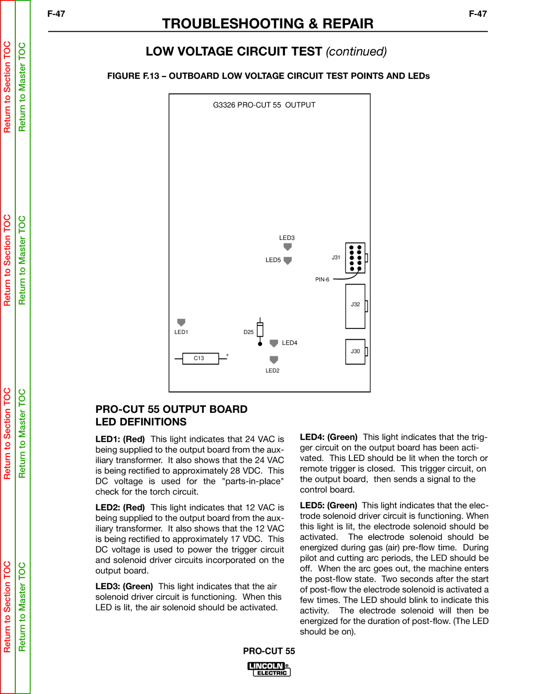
FIGURE F.13 – OUTBOARD LOW VOLTAGE CIRCUIT TEST POINTS AND LEDs
G3326 PRO-CUT 55 OUTPUT
Return to Section TOC
Return to Master TOC
LED1
C13
LED3
| LED5 | J31 |
|
| |
|
| |
|
| J32 |
| D25 |
|
|
| LED4 |
+ |
| J30 |
|
| |
| LED2 |
|
Return to
Return to Section TOC
Return to
Return to Master TOC
LED1: (Red) This light indicates that 24 VAC is being supplied to the output board from the aux- iliary transformer. It also shows that the 24 VAC is being rectified to approximately 28 VDC. This DC voltage is used for the
LED2: (Red) This light indicates that 12 VAC is being supplied to the output board from the aux- iliary transformer. It also shows that the 12 VAC is being rectified to approximately 17 VDC. This DC voltage is used to power the trigger circuit and solenoid driver circuits incorporated on the output board.
LED3: (Green) This light indicates that the air solenoid driver circuit is functioning. When this LED is lit, the air solenoid should be activated.
LED4: (Green) This light indicates that the trig- ger circuit on the output board has been acti- vated. This LED should be lit when the torch or remote trigger is closed. This trigger circuit, on the output board, then sends a signal to the control board.
LED5: (Green) This light indicates that the elec- trode solenoid driver circuit is functioning. When this light is lit, the electrode solenoid should be activated. The electrode solenoid should be energized during gas (air)