Return to Section TOC
Return to Master TOC
TROUBLESHOOTING & REPAIR
CONTROL BOARD REMOVAL AND REPLACEMENT (continued)
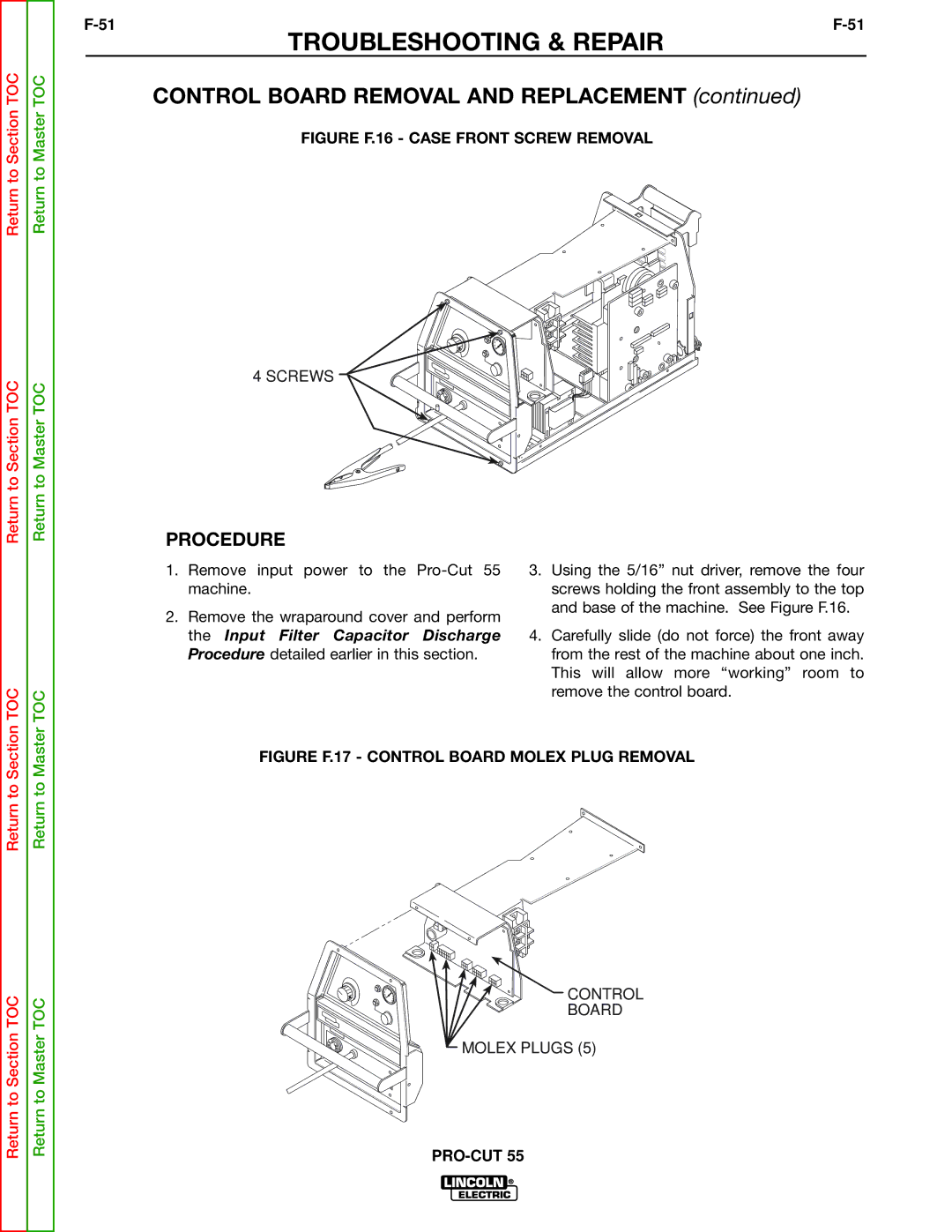
FIGURE F.16 - CASE FRONT SCREW REMOVAL
4 SCREWS
Return to Section TOC
TOC
Return to Master TOC
TOC
PROCEDURE
1.Remove input power to the
2.Remove the wraparound cover and perform the Input Filter Capacitor Discharge Procedure detailed earlier in this section.
3.Using the 5/16” nut driver, remove the four screws holding the front assembly to the top and base of the machine. See Figure F.16.
4.Carefully slide (do not force) the front away from the rest of the machine about one inch. This will allow more “working” room to remove the control board.
Return to Section
Return to Section TOC
Return to Master
Return to Master TOC
FIGURE F.17 - CONTROL BOARD MOLEX PLUG REMOVAL
![]()
![]() CONTROL
CONTROL
BOARD
MOLEX PLUGS (5)