to Section TOC
to Master TOC
TROUBLESHOOTING & REPAIR
LOW VOLTAGE CIRCUIT TEST (continued)
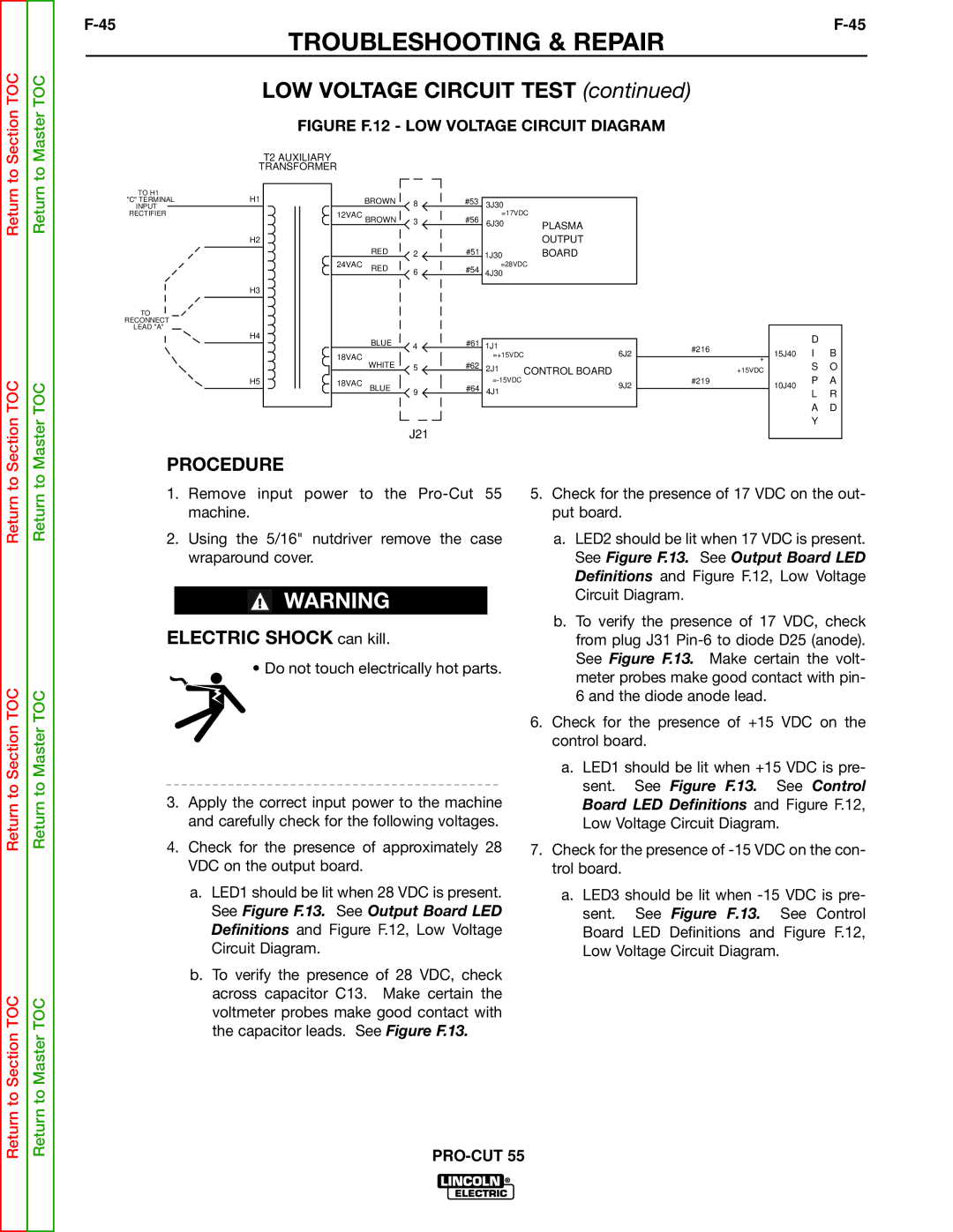
FIGURE F.12 - LOW VOLTAGE CIRCUIT DIAGRAM
T2 AUXILIARY
TRANSFORMER
TO H1
"C" TERMINALH1 INPUT
RECTIFIER
H2
H3
TO
RECONNECT
LEAD "A"
H4
H5
| BROWN | 8 | #53 | 3J30 |
|
|
|
|
|
|
|
12VAC BROWN | 3 | #56 | =17VDC |
|
|
|
|
|
| ||
6J30 |
| PLASMA |
|
|
|
|
| ||||
|
|
|
|
|
|
|
|
|
| ||
|
|
|
|
|
| OUTPUT |
|
|
|
|
|
| RED | 2 | #51 | 1J30 |
| BOARD |
|
|
|
|
|
24VAC | RED | 6 | #54 | =28VDC |
|
|
|
|
|
| |
| 4J30 |
|
|
|
|
|
|
| |||
|
|
|
|
|
|
|
|
|
|
|
|
|
|
|
|
|
|
|
|
|
|
|
|
| BLUE |
| #61 |
|
|
|
|
|
| D |
|
| 4 | 1J1 |
|
| #216 |
|
|
| |||
|
| 6J2 |
| 15J40 | I | B | |||||
18VAC |
|
|
| =+15VDC |
| ||||||
|
|
|
|
| |||||||
WHITE |
|
|
| + | |||||||
| #62 |
|
|
|
|
| S | O | |||
| 5 | 2J1 | CONTROL BOARD |
| +15VDC |
| |||||
|
|
|
|
|
| P | A | ||||
18VAC | BLUE |
| #64 |
| 9J2 | #219 |
| 10J40 | |||
9 | 4J1 |
|
|
|
|
| |||||
|
|
|
|
|
| L | R | ||||
|
|
|
|
|
|
|
|
|
| A | D |
|
|
|
|
|
|
|
|
|
| ||
|
|
|
|
|
|
|
|
|
| Y |
|
|
| J21 |
|
|
|
|
|
|
|
|
|
Return to
Return to Section TOC
Return to Section TOC
Return to
Return to Master TOC
Return to Master TOC
PROCEDURE
1.Remove input power to the
2.Using the 5/16" nutdriver remove the case wraparound cover.
WARNING
ELECTRIC SHOCK can kill.
• Do not touch electrically hot parts.
3.Apply the correct input power to the machine and carefully check for the following voltages.
4.Check for the presence of approximately 28 VDC on the output board.
a.LED1 should be lit when 28 VDC is present. See Figure F.13. See Output Board LED Definitions and Figure F.12, Low Voltage Circuit Diagram.
b.To verify the presence of 28 VDC, check across capacitor C13. Make certain the voltmeter probes make good contact with the capacitor leads. See Figure F.13.
5.Check for the presence of 17 VDC on the out- put board.
a.LED2 should be lit when 17 VDC is present. See Figure F.13. See Output Board LED Definitions and Figure F.12, Low Voltage Circuit Diagram.
b.To verify the presence of 17 VDC, check from plug J31
6.Check for the presence of +15 VDC on the control board.
a.LED1 should be lit when +15 VDC is pre- sent. See Figure F.13. See Control Board LED Definitions and Figure F.12, Low Voltage Circuit Diagram.
7.Check for the presence of
a.LED3 should be lit when