Return to Section TOC
Return to Master TOC
TROUBLESHOOTING & REPAIR
AIR/GAS SOLENOID TEST (continued)
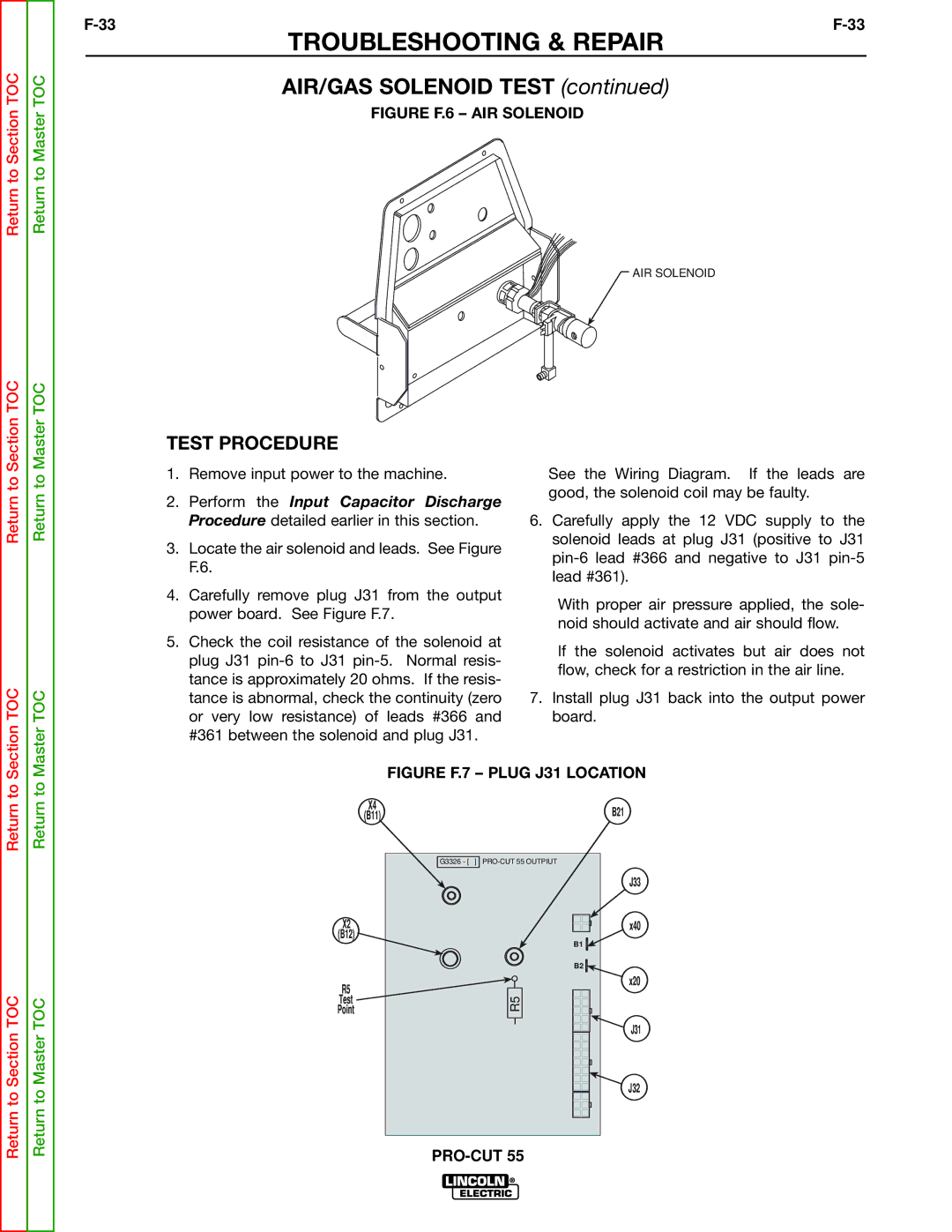
FIGURE F.6 – AIR SOLENOID
AIR SOLENOID
Return to Section TOC
Section TOC
Return to Master TOC
Master TOC
TEST PROCEDURE
1.Remove input power to the machine.
2.Perform the Input Capacitor Discharge Procedure detailed earlier in this section.
3.Locate the air solenoid and leads. See Figure F.6.
4.Carefully remove plug J31 from the output power board. See Figure F.7.
5.Check the coil resistance of the solenoid at plug J31
See the Wiring Diagram. If the leads are good, the solenoid coil may be faulty.
6.Carefully apply the 12 VDC supply to the solenoid leads at plug J31 (positive to J31
With proper air pressure applied, the sole- noid should activate and air should flow.
If the solenoid activates but air does not flow, check for a restriction in the air line.
7.Install plug J31 back into the output power board.