Return to Section TOC
Return to Section TOC
Section TOC
Return to Master TOC
Return to Master TOC
Master TOC
TROUBLESHOOTING & REPAIR
PRIMARY POWER BOARD RESISTANCE TEST AND
CAPACITOR VOLTAGE TEST (continued)
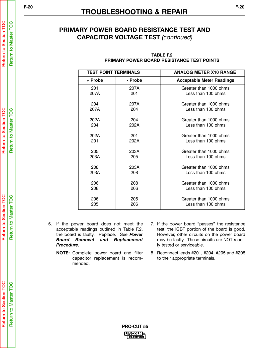
TABLE F.2
PRIMARY POWER BOARD RESISTANCE TEST POINTS
TEST POINT TERMINALS | ANALOG METER X10 RANGE | |
|
|
|
+ Probe | - Probe | Acceptable Meter Readings |
|
|
|
201 | 207A | Greater than 1000 ohms |
207A | 201 | Less than 100 ohms |
204 | 207A | Greater than 1000 ohms |
207A | 204 | Less than 100 ohms |
202A | 204 | Greater than 1000 ohms |
204 | 202A | Less than 100 ohms |
202A | 201 | Greater than 1000 ohms |
201 | 202A | Less than 100 ohms |
205 | 203A | Greater than 1000 ohms |
203A | 205 | Less than 100 ohms |
208 | 203A | Greater than 1000 ohms |
203A | 208 | Less than 100 ohms |
206 | 208 | Greater than 1000 ohms |
208 | 206 | Less than 100 ohms |
206 | 205 | Greater than 1000 ohms |
205 | 206 | Less than 100 ohms |
|
|
|
Return to
6.If the power board does not meet the acceptable readings outlined in Table F.2, the board is faulty. Replace. See Power
Board Removal and Replacement Procedure.
NOTE: Complete power board and filter capacitor replacement is recom- mended.
7.If the power board “passes” the resistance test, the IGBT portion of the board is good. However, other circuits on the power board may be faulty. These circuits are NOT readi- ly tested or serviceable.
8.Reconnect leads #201, #204, #205 and #208 to their appropriate terminals.
Return to Section TOC
Return to Master TOC